Ciro-flex TLR
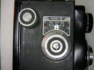
The Ciro-flex is an American made TLR manufactured during the 1940s and '50s. The Ciro camera company was purchased by Graflex and the Ciro-flex continued to be manufactured as the Graflex 22. Altogether, there were six different Ciro-flex models, A through F. The model A has a slightly different focusing mechanism, and is not quite as common. The B and C models have a non-synchronized shutter while the D, E, and F models have flash synchronization. The B and D models use the simple Alphax shutter while the C, E, and F models use the high-quality Rapax shutter. Early versions of these cameras have a parallax correction frame under the ground glass. In later models, the frame was replaced with a fresnel lens in order to help brighten the focussing screen. Overall, these are no-frills cameras with only a simple knob winder, no double exposure prevention or automatic film counter. However, they are sturdy cameras with good lenses and shutters. The model F has an excellent four-element lens that is quite sharp. All of these cameras are capable of taking very nice pictures and are still very usable for low-budget medium format photography.
Unfortunately, you will almost always find these cameras in terrible condition. The lenses, reflex mirror and ground glass are usually hazy and the shutter sticky or inoperative. In addition, the steel body will rust anywhere the paint has chipped off, and, often these cameras look like they are well beyond repair. However, as long as the lens isn't damaged from fungus, a Ciro-flex can almost always be brought back to life. The rust on the body doesn't really affect the performance of the camera; it just looks bad. These are easy cameras to work on and make an excellent first project if you are interested in learing how to repair a TLR. In addition, these cameras can be bought for very little money (often $20-30) and so if you are willing to put in a little work, you can have a nice medium-format camera for a very low price.
In this article, I show disassembly of the focus mechanism. Usually, this isn't necessary. The focus cam can be cleaned using cotton swabs dampened with cigartte lighter fluid by reaching in from the back of the camera. On this camera, there was some dried out grease and I needed to soak the parts in solvent to get everything clean. As you can see, there isn't much else to disassemble on the Ciro-flex.
A very good book on the Ciro-flex camera, and TLR usage in general, is PHOTOGRAPHY with the Ciro-flex by Bruce Downes. I have uploaded a 300dpi scan of the information in a Ciro-flex brochure. This describes the features of models B through F and shows the original prices.
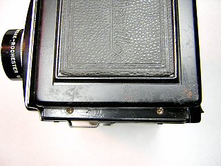 |
To clean the focusing screen and/or reflex mirror, remove the four screws around the top cover and lift the cover off.
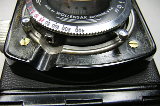
NOTE: on early versions of the Ciro-flex, with the parallax correction frame, you will not be able to lift the viewing hood off until the frame's connecting lever is disconnected. In order to disconnect the lever, you need to remove the front panel, rotate the focus to the shortest distance and then remove the screw located on the right side of the lens standard.
|
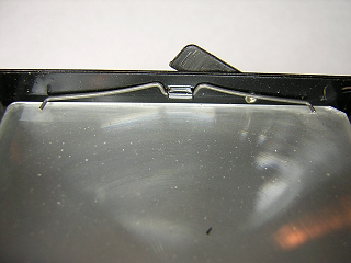 |
The focusing screen and fresnel lens are held in place by two spring clips. Turn the hood over and remove the two clips. You will need to then slightly spread the frame to allow the screen and lens to fall out.
There are also four tabs on the frame that may be bent inward slightly to help hold everything in place. On cameras with the parallax frame, these tabs hold the frame together. Bend the tabs straight to allow the frame to separate.
|
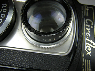 |
With the hood off, you can reach the rear element of the viewing lens for cleaning. However, these lenses seem to get a coating of haze on the inner surfaces, and may need to be disassembled to get them clean. In addition, if you need to disassemble the focus, you will need to remove this lens in order to get the front panel off.
To remove the viewing lens, loosen the retaining ring at the base of the lens, then unscrew the lens assembly from the body. This ring is often tight. You can use a soft-jaw plier to remove it. It is easier to remove this lens after the shutter is removed from the camera. If you are going to remove the shutter, wait until the shutter has been removed before removing the viewing lens.
The outer lens elements are held in place by screw-in retaining rings that have no slots for a spanner. Use a rubber furniture leg cup to unscrew the rings. These rings may be stuck from oxidation. A small amount of solvent, such as alcohol or laquer thinner, will help loosen the rings.
To adjust the focus on the viewing lens, just loosen the retaining ring and rotate the lens until the image on the focusing screen matches the taking lens focus. Retighten the retaining ring when done.
|
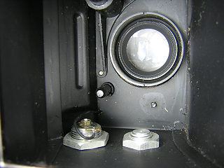 |
The shutter is held in place by a retaining ring accessible through the back. On models without a flash connector, just unscrew the retaining ring and the shutter will lift out.
On models with flash, you need to disconnect the flash wiring before removing the shutter. Open the back and unsolder the flash connector you find there. There is another flash wire under the front panel that will need to be unsoldered as well. Remove the front panel to gain access to the second wire.
|
 |
To remove the front panel, first peel off the leatherette from the front. The leatherette is made of paper and you should not use any liquid to try and loosen the glue. It is quite common for the leatherette to disintegrate when you try to remove it, so take that into consideration before deciding the remove the front panel. Remove the four screws and the front panel can then be lifted off. On the model F, you may need to loosen the shutter retaining ring slightly in order to work the panel around the shutter.
On flash models, you can now reach the body connecting wire to unsolder it.
|
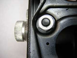 |
To remove the focus for cleaning, first remove the front cover, shutter and viewing lens. Unscrew the hex nut and the lens mounting plate will lift off.
|
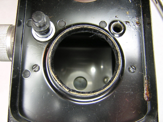 |
The next panel rarely needs to be removed. You can remove it for cleaning if needed, or if you want to remove all the old leatherette. Remove the four screws and the plate will lift off. There is a felt washer underneath the panel that goes around the hole that the guide post for the lens plate moves in.
|
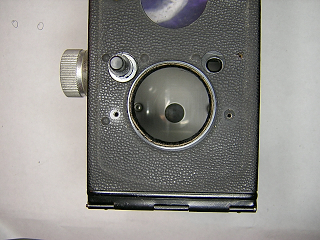 |
The focus bracket is held to the body with four screws located underneath the leatherette. You need to cut into the leatherette to expose the screws and then remove them. It usually isn't necessary to remove this bracket since it can be cleaned once the forcus shaft is pulled out from the back. (See next picture.) However, if you need to remove the focus cam, this bracket has to come out first.
In the previous picture, note the four holes for the screws that hold the focus bracket. These screws can be removed without removing this panel.
|
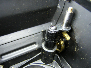 |
Remove the screw in the end of the focus shaft and lift the guide and shaft out.
Note that the guide that sits against the focus cam is not exactly perpendicular to the camera body. It must be positioned so that the guide does not bind against the cam when the cam is rotated to the short focus position. This is usually when the guide is at an angle of about five degrees to the camera body. To reinstall the focus shaft, insert the shaft and guide but don't tighten the hex nut on the front panel. Rotate the focus to the short position and allow the guide to rotate to where it doesn't bind. Hold the guide in place while tightening the hex nut on the front.
|
 |
To remove the focus cam, loosen the screw in the center of the focus knob and lift the knob off. The cam can be removed from the inside of the camera.
The focus cam needs considerable lubrication on both the inside and outside surfaces.
To adjust the focus, set the focus so that the image at the film plane is sharp at infinity, then loosen the screw in the middle of the knob and turn the knob against the infinity stop.
|
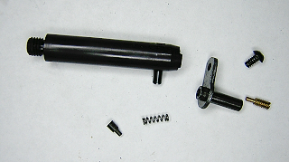 |
This picture shows the parts of the focus shaft and guide. There is a spring tensioner in the guide that puts pressure on the guide to prevent slap-back of the focus.
Lightly lubricate the shaft where it goes through the mounting bracket
|
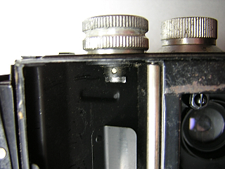 |
To remove the wind knob, push out the tapered pin in the spool shaft and then pull the collar off, then reach in and pull the coiled spring out.. The knob and shaft come out together. There is a spring inside the knob that prevents the winder from being turned backwards. One end of this spring is bent so that it fits into the slot in the tube the winder goes through.
You will need to put a liberal coating of grease on the inside of the knob. This will give the knob a nice smooth feel and will also stop the winder from squeaking.
|
Notes
If you need to remove the back, push out the steel rod in the hinge and the back will separate.
The two film guide rollers may have rust on them and need to be removed for cleaning. Slightly bend the bracket that holds the ends of rollers and then pop the rollers out.
|