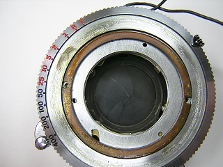
The Wollensak Rapax shutter is an American made shutter used on the Ciro-flex TLR
and a variety of field, view and press cameras as well.
The Rapax shutter was produced in a variety of configurations, some with flash synchronization
and some without. The shutter shown here has a single X synchronizer. Another model was produced
with a synchronizer that could be switched between M-F-X and OFF.
 |
Begin by removing the front and rear lens cells. Next remove the two screws in the faceplate
and lift the faceplate off.
Remove the brass spacer and the speed control ring. When removing the speed ring, you will need
to pull the aperture indicator back slightly. It is a good idea to put a piece of masking tape
over the speed ring underneath the aperture indicator in order to avoid scratching the ring
with the aperture indicator.
Clean the old grease off the speed setting ring and then lubricate it with a light coating of
grease during reassembly. I like using Nyogel light damping grease for this as it gives the
speed control a nice dampened feel and prevents accidently moving the speed ring when cocking
and releasing the shutter.
|
 |
The shutter cover is held in place with four screws. When removing the screws, examine them closely.
The screw next to the slot that controls the shutter speed is shorter and must be replaced in that
location. In addition, one of the screws will typically have a portion of the threads filed away.
This is done so that the screw does not interfere with the operation of the shutter. That screw
needs to be replaced in the same hole it was removed from.
Note how the retard control pins fit into the appropriate slots in the control ring.
The T and B pins fit on the inside of the speed cam. The slot in the speed cam shown
at the upper left mates with a stud on the back of the speed setting ring.
The cover is a tight fit and usually you will have to pry it off the shutter base with
a small screwdriver inserted into the slot where the shutter release is.
Turn the cover plate over and remove the screw holding the speed setting cam. The cam can be
lifted off for cleaning. The cam should be lubricated with a light coating of grease.
|
 |
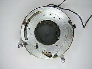
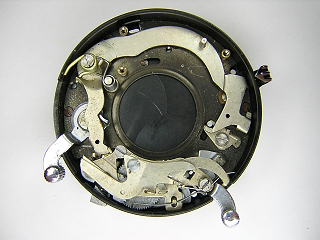
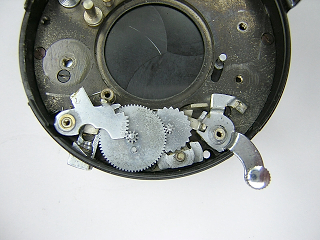
This image shows the entire clockworks with the top cover removed. The retard mechanism is
at the bottom of the picture. The flash syncronizer is at the top.
|
 |
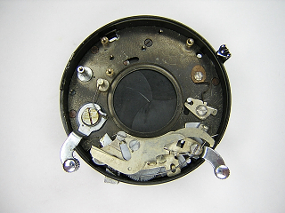
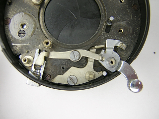
Remove the flash contacts then remove the three screws holding the synchronizer
and lift the synchronizer off. When removing the contacts don't lose the insulating
washers. There is an insulator on the top and bottom of the first screw and another
insulator on the second screw.
Note how one spring sits against the side of the case. The synchronizer is operated
by a stud on the main activating arm that projects up into the synchronizer. You need to
pull back on the synchronizer mechanism to free it from the stud. Optionally, you can
unhook the spring to release the tension on the mechanism.
|
 |
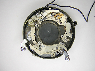
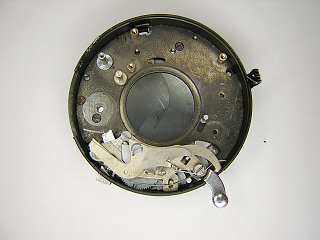
Remove the screw on top of the main spring, then remove the main spring and booster springs.
These are powerful springs and can be difficult to remove. Be sure to keep your hand over the
springs when removing and installing them as they will tend to fly off with a great deal of
force once they are unhooked. It's a good idea to put a piece of heavy tape (e.g. duct tape)
over the shutter case next to the main spring. This will help prevent scratching the case as
the spring unwinds.
With the springs removed, you can lift the main activating arm off.
When reinstalling the springs, put a tiny amount of grease where the short leg of
each spring sits against the main activating arm. Set the short end of the spring in
place first, then rotate the spring to the proper position. It takes a fair amount of
force to get the main spring back into position. Don't replace the screw until the spring
is properly seated in place as the force of the main spring is sufficient to strip the
screw right out,
|
 |
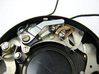
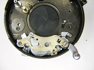
Remove the screw in the blade operating lever and lift the lever off. Remove the screw
in the blade opening spring and remove the spring. Be very careful not to distort the
spring. This spring "kicks" the blade operating lever during opening so that the blades
snap open fully. If this spring is not functioning properly, the blades may not open
completely.
Unhook the spring on the shutter cocking lever then remove the screw, spring, lever
and washer underneath. In this picture, the spring has become displaced. It should sit
in the slot in the base of the booster spring post. Lubricate the bottom side of the
cocking lever during reassembly.
|
 |
Unhook and remove the spring on the T/B levers and remove the screw in the middle of the levers
then lift the T/B levers off.
|
 |
Unhook the pallet spring where it sits against the case and let it rotate back out of the
way. Then remove the three screws holding the retard cover and lift the cover off. Remove the
spring from the shutter release lever.
|
 |
Unhook the spring on the retarding lever and remove the lever, intermediate gear, start wheel
and pallet. Note the stud on the intermediate gear. This has to mate with the slot in the
retarding lever when the retarding lever is driven to its resting position. On reassembly,
pull the retarding lever down against the case and then rotate the intermediate gear into
the proper position.
|
 |
Remove the screw in the cable release lever and remove the lever. Remove the screw in the
pallet bracket and remove the bracket. Lift the shutter relase lever off.
Remove the screw in the cable release socket and push the socket out through the case.
|
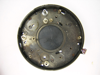 |
Remove the four screws around the outside of the base and the three screws just inside them.
The inside screws are shorter. The base can now lift off.
|
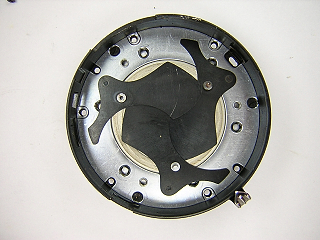 |
Remove the three shutter blades and blade drive ring.
|
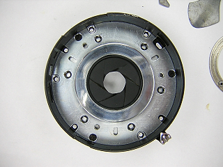 |
Remove the screws holding the diaphgram and lift the diaphragm out. The diaphragm blades
are permanently attached. You can swing the blades out into a "fan" to make it easy to clean
any grease off the blades. When reinstalling the diaphragm, push the blades in so that they
are slightly inside the opening, then insert a pencil into the lens opening and move the
pencil around until the blades match the opening. This is the maximum aperture position and
the studs on the blades should match the aperture control ring when the ring is set to the
minimum position.
|
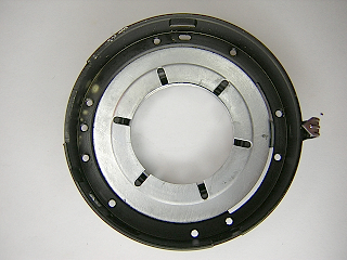 |
Rotate the aperture control ring until the indicator is sitting in the cutout in the
shutter case. Lift up the ring and slide the ring out.
Lubricate the raised portion of the ring where it sits against the case and the
diaphragm cover plate. Don't get any grease on the part of the ring that mates with the
blades.
|