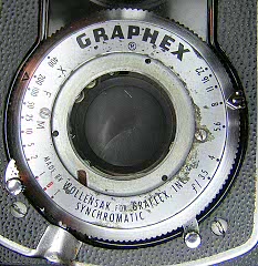
Graphex Shutter
The Graphex shutter is the Graflex brand for the Wollensak Rapax shutter. It is an American made shutter used on a variety of field, view and press cameras as well as the Graflex 22 TLR. The Graflex 22 is a variant of the Ciro-flex TLR and the same shutter was used on the Ciro-flex, labeled as Rapax.
The Graphex/Rapax shutter is a rugged, high-quality shutter and is very reliable. It was available in several sizes and with or without flash synchronization. Versions intened for use on view cameras have a press focus lever as well.
Like the Alphax, the Graphex/Rapax is disassembled from the front and can usually be serviced without removing it from the camera. In the pictures below, you'll see that the shutter has been left on the camera and is only disassembled far enough to clean the escapement. If you are going to completely disassemble the shutter, you will want to remove it from the camera first.
I have scanned in the theory of operation section and parts diagram from the service manual. Click here to download a ZIP file of these scans. Each page is a separate PDF file and you will need Adobe Acrobat reader to view them. The parts diagram shows lubrication points. Points marked "GL" are lubricated with grease. Points marked "LO" are lubricated with oil.
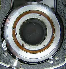
The shutter shown below is from an Graflex 22 TLR.
 |
Remove the front lens then remove the two screws in the faceplate and lift it off. You may also want to remove the rear lens assembly to avoid getting grease or solvent on the lens.
|
 |
Remove the spacer then lift up the speed ring slightly at the speed indicator and slide the ring out to clear the aperture pointer. It may be necessary to pull the aperture pointer out slightly to get the speed ring off. I also like to put a piece of masking tape on the ring under the aperture pointer to avoid scratching the ring.
|
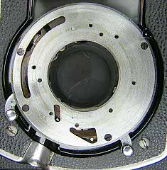 |
Remove the four screws from the top cover. Note that one of the screws is shorter and one of the screws may have a flat side in the threads. Be sure to reinstall each screw in the same hole it was removed from.
With the screws out you can pry the cover off. The cover has two "dimples" in it around the release lever and usually you will have to insert a small screwdriver between the cover and base to pry it out.
Turn the cover over and you will see the screw that holds the speed setting cam. Remove the screw and remove the cam for cleaning and lubrication.
|
 |
At this point you may be able to just flush clean the escapement and trigger without any further disassembly.
On shutters with full flash syncronization, you will see the flash delay retard on the right of the shutter. This can be left in place or removed for cleaning. If you are doing a complete disassembly, remove the flash delay retard next.
|
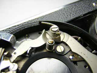 |
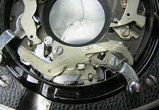
This is a closeup of the main lever spring and high speed spring. These are powerful springs and difficult to remove and reinstall. If you need access to the shutter blades or diaphragm, you will have to remove these springs and the main lever. On this shutter, the only problem is a sticky retard, so I am going to leave the main lever in place.
|
 |
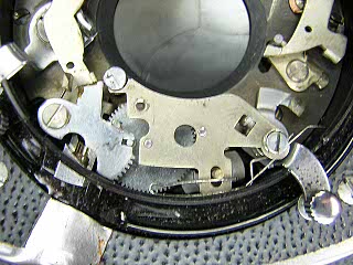
Unhook the spring on the B lever and then unhook the opposite end of the spring where it sits on the T lever. Remove the screw that holds the T and B levers and then lift the levers off. (The B lever is the one on top.)
At the upper right in the picture you can see the blade lever and part of the blade lever spring that is underneath the main lever. You can remove the blade lever and clean it if it is sticky. The blade lever spring is a flat copper spring that sits in a slot of the blade lever and boosts the blades open and shut. If the blades don't open fully or don't close quickly, this spring is either worn out or sticky from old lubricant. If you remove either of these parts, be careful not to bend the spring and also insure during reassembly that it is sitting in the notch on the blade lever. |
 |
Remove the screw and spring on the release lever. Remove the screw at the end of the retard cover and lift the cover off. The release lever spring will need to be pulled back gently to get the cover off. With the cover off, you can then remove the spring from the release lever. Note that this spring provides tension to the pallet. If the spring gets bent or worn out the shutter may not run at the correct speed.
|
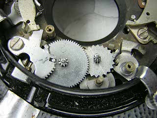 |
Remove the screw on the retarding lever and lift the lever and spring out. Remove the center gear, pallet gear and pallet.
Note how the stud on the center gear fits into the slot of the retarding lever. These have to be reassembled so they mate correctly.
|
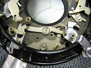 |
Remove the screw in the cable release lever and lift the lever out. Remove the screw in the pallet lever and lift the lever out. Lift out the release lever.
|
Notes
When cleaning, make sure there is no residue of old grease in the bearings for the escapement gears. I insert a toothpick dampened with solvent into each hole and twirl it around until the toothpick comes out clean.
Lubricate each of the parts of the retard with light oil. The service manual suggests toching the end of the gears to a piece of felt dampened with oil. I use a toothpick dipped in oil and inserted into each of the bearings to do this.
Lubricate the end of the main lever where it strikes the T/B levers and the retard lever.
Lubricate the cocking lever and release lever where they rub against the case
Lubricate the speed setting cam surface that contacts the shutter cover
Lubricate the speed setting ring where it rubs against the shutter cover and faceplate.
When installing the shutter cover make sure the T and B tabs and the sector gear tab fit into the appropriate slots.
When installing the speed setting ring, make sure the stud fits into the slot in the speed cam.
|