Simple Mechanical Diaphragm
In all but the simplest of leaf shutters you will find an adjustable diaphragm. The diaphragm is the part of the shutter (or lens) that varies in opening size (aperture) to control the amount of light that reaches the film. In combination with the shutter speed, the size of the opening determines the film exposure. By making the diaphragm variable a wide range of exposures are available.
In addition to controlling the exposure the diaphragm aperture affects the depth of field. As the opening gets smaller the circle of confusion produced by a slightly out of focus point of light will get smaller as well. When the circle of confusion is small enough the eye cannot distinguish between the circular shape and a precise point. Then end result is that the image appears sharp even though it is slightly out of focus.
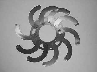
The basic diaphragm consists of a set of sicle-shaped blades (Kodak calls them wings) that slide in and out from the center of the lens. One end of the blade is fixed in position while the other end is free to move back and forth. As the aperture setting control is moved a ring rotates causing the non-fixed end of the blade to move with the ring. Because the free end of the blade is moving in a circle the end of the blade moves along an arc. The result is that the blades move in such a way as to cover more or less of the lens opening. The overlap of the curved blades results in a circular opening.
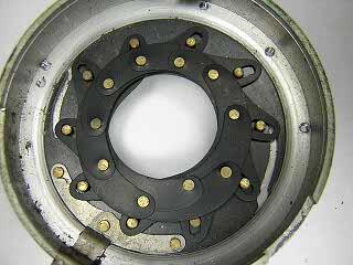
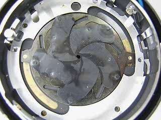
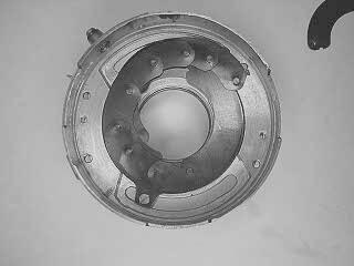
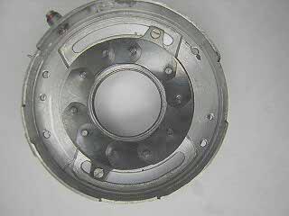
The pictures to the right show the view of a Prontor shutter diaphragm from the back with all but three of the blades removed. The fixed end of the blade is located underneath and is held in position by a small stud that goes into a hole in the cover plate. The movable end of the blade is on top in the picture and is held into the slot in the control ring by a small stud. In the first picture the diaphragm is fully open. In the second picture the control ring has been rotated clockwise. Except for the attachment of a control lever, that's all there is to a manually operated diaphragm.
A simple diaphram could have as little as two blades. Most diaphragms on older shutters have eight, ten or even twelve blades. As a general rule, the more blades there are in the diaphragm the more rounded the opening will be. The shape of the opening is immaterial to the exposure since it is only the area of the opening that matters. However, the shape does affect the shape of the circle of confusion on the film. The more rounded the opening is the more rounded an out of focus point will be. Normally the shape of the diaphragm is not visible to the eye when looking at a photograph. However, when a light source is shining directly into the lens, the reflections of lens flare will show up with the same shape of the diaphragm. The same is true for bright, out of focus areas in the image.
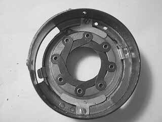
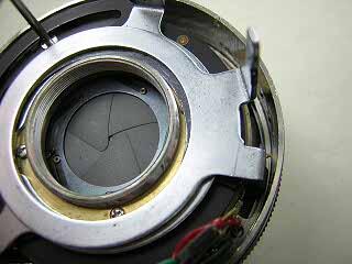
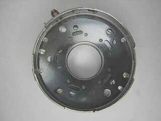
The diaphragm is usually located behind the shutter blades but can just as easily be located in front. The Kodak Ball bearing shutter shown to the right has the diaphragm in front of the shutter blades. Note that instead of studs inserted into the blades to hold them in position, holes are punched out into a flange that fits into the control ring slots. The back of the blades are permanently attached to the inner shutter base. The diaphragm from the Ilex Precise also has the blades permanently attached. In addition, the blades in the Ilex are made of thin cardboard rather than steel. It's a good idea to check the diaphragm on an inexpensive camera before dunking the whole assembly into a solvent!
|
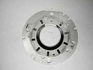
Blades fully open.
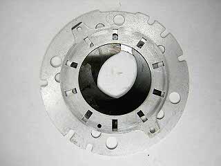
Blades partially closed.
Blades completely closed.
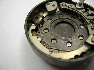
Kodak Ball Bearing shutter with diaphragm in front of shutter. Instead of pins on the blades there are flanges made by punching out holes in the blades. The blades are permanently attached to the inner shutter base.
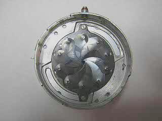
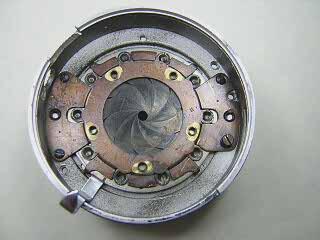
Diaphragm from an Optima shutter
An Ilex precise from an Argus A.
Diaphragm from an alphax shutter
|
Linear Aperture Scale Diaphragm
If you look at the aperture scale on older shutters you see that the numbers are not equidistant from each other. The scale is compressed at the small openings (large f-stop) and and spread out at the wide openings (small f-stop). The reason, of course is that the exposure is determined by the area of the circle. The linear motion of the blades means that you vary the diameter of the opening linearly with the movement of the aperture control ring. The operation of the diaphragm is linear but the variation in exposure must be exponential.
During the 1950's shutter manufacturers began to change the diaphragm in order to provide a linear aperture scale. This allowed the aperture to be coupled with the shutter speed dial so that once the ratio of the speed to aperture was set, the photographer could change both the speed and aperture with one control ring. This was often done to correspond with the "LV" scale that was common on light meters. An equidistant movement of the aperture control had to produce an exponential change in the blade position. This was accomplished by redesigning the blade shape and the controling groove in the operating ring.
|
|
Automatic Flash Settings
When using a flash the exposure is controlled by the amount of light the flash puts out, the distance to the subject, and the aperture. The shutter speed in most cases does not affect exposure. With a linear scale aperture it became possible to link the aperture with a guide number setting and rangefinder to automatically select the proper aperture for flash photography. On the Canonent, some of the Minolta Hi-Matic cameras, and other cameras from the 1970s, there is a special setting on the shutter for this type of operation. |
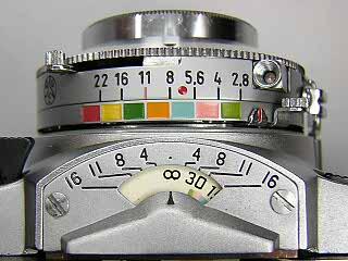
This Graflex Graphic 35 had a color coded system that helped to set the aperture for flash photography. The GN was set with a dial on the bottom of the shutter, shifting the relationship between the colors and the aperture settings. The distance scale indicated the appropriate aperture by the color code.
|
Auto-exposure Diaphragm
Once the liner scale aperture was developed it was possible to couple the diaphragm to a built-in light meter to achieve a shutter priority auto-exposure system. A lever that pushes the diaphragm control ring is coupled to a serrated plate that drops down as the shutter release is pressed. The searrated blade is stopped by a bar connected to the meter. As the meter changes with the available light, the aperture is automatically set. This type of diaphragm needs very light blades that act more like shutter blades than the traditional diaphgram blades. In addition to the shape of the blades, the number of blades is usually reduced and the blades no longer interleave but lay on top of each other.
This type of linear control with the aperture position set automatically also made possible the auto-diaphragm system used on many SLR cameras with full aperture focusing and stop down metering. With that type of diaphragm system combined with electronic shutter speed control, many SLR cameras began to introduce an aperture priority exposure system.
Since the diaphragm blades now must move quickly under control of a lightweight spring, any oil or grease on the blades will cause the diaphragm to stop working. On auto-exposure systems, this may even prevent the shutter from operating.
With the aperture now controlled automatically, some shutter manufacturers went even further and eliminated the diaphragm altogether. The shutter was redesigned so that the amount the blades are allowed to open was controlled by the auto-exposure system. Thus the exposure system on cameras went from relying mostly on the aperture setting for expsure control due to the limited number of shutter speeds available, to relying entirely on a variable speed and variable opening shutter with the diaphragm discarded altogether.
|
A Copal SV that needs a lot of cleaning! On a manual diaphgram, oil on the blades looks bad but won't affect the operation of the diaphragm unless the oil has become dried out and sticky. On an automatic diaphgram any oil on the blades must be removed for the camera to function properly. The oil you often see on the blades leaks out of the lens focus grease. The aperture should have NO oil or grease in it.
Seiko LA with automatic exposure. One of the rings cocks the shutter while the other is connected to the shutter release and simultaneously pushes on a lever that opens the aperture.
|
Disassembly of a Diaphragm
Disassembly of a diaphragm is usually quite easy. You remove any screws from the cover plate, lift the cover off, then lift out the blades or blade assembly. If needed, remove the screws that hold the operating ring to the control ring as well and lift the operating ring out. You can then carefully clean each piece by wiping with a paper towel dampened with solvent. Alternatively, you can immerse all pieces into solvent and then wipe them off with a dry towel.
It is common pratice to make a scratch mark on the front side of the cover to indicate which side goes to the front and also the orientation of the cover in the case. This saves having to try to figure out which holes match up when reinstalling the cover.
When taking the blades out of the diaphragm, examine them to see if the two ends of the blade are different. Make a note of any differences as it may be important to get the correct end of the blade facing towards the rear of the shutter.
Putting the diaphragm back together can be simple or extremely difficult depending on the design. For diaphragms where the blades are permanently attached, it is simply a matter of positioning the blaeds properly and then placing the assembly back into the shutter base. For auto-exposure shutters, the blades are usually few in number and simply lay on top of each other the same way shutter blades do. However, for the older manual diaphragms with a large number of blades, putting everything back together can be very frustrating.
|
Reassembly of a Diaphragm
Begin reassembly by placing the operating ring back into place in the shutter base. Make sure the ring is placed at its maximum aperture position.
|
Shutter base with operating ring in position.
|
|
Begin placing the blades making sure to seat the proper end of the blade into the slot or hole in the operating ring. On some designs, both ends of the blade are the same and it doesn't matter which end goes down. On other designs, the ends of the blade or the length of the studs may be different. Hopefully you took note of this during disassembly!
Carefully overlap each successive blade trying to get each as close to the position for maximum aperture as you can.
|
 |
|
When you reach the place where the last blades meet the first blades, you need to carefully lift the first blades up in order to slide the next blade in underneath. This can be frustrating as the blades are very lightweight material and will tend to shift position when you move one of them.
A trick that can be used is to put a very tiny amount of light grease into each slot or hole in the operating ring. This will hold the blade in position during reassembly. However, you will need to flush all the grease out from the diaphragm after it is back together. Another possibility is to use a drop of solvent on the blades to help hold them together and prevent movement. If the blades are completely clean, the solvent should dry without leaving any residue.
With practice, patience and a steady hand, you can put these back together without anything to hold them in position.
|
 |
|
Once you have all the blades installed push them carefully into a round shape that matches the maximum aperture opening. Try to get the blades as evenly spaced as possible.
|
 |
|
Carefully place the cover plate down onto the diaphragm. This has to be done gently so that you do not bump the blades and cause them to get out of position. You need to get all the studs of the blade into the proper hole in the cover plate. Usually this will mean holding the cover in place with your finger while reaching in and gently nudging the blade into position with a toothpick or similar tool. To avoid getting fingerprints on the cover, use a paper towel or latex glove to cover your fingers.
To help get the blades to drop into the holes, you can very gently move the aperture control back and forth while keeping slight pressure on the cover. Don't force the control as you can bend a blade or break a stud on a blade if the blade is not in its hole. As the blades drop into place you can hear a slight click sound.
When all the blades are in proper position and moving in and out smoothly, install the cover screws. Be sure to wipe off any smudges on the cover or blades.
|
 |
|
An alternative method for reassembly is to lay the cover front side down on the table and then lay the blades onto the cover spread out in a fan shape. Next slowly work each blade in towards the center while overlapping each blade. Insert a pencil into the center of the cover and move it around to get all the blades to match the aperture.
Pick up the cover and blades and then lay the shutter base on top.While holding the cover in place with your fingers, turn the shutter over. Make sure all the blades are in position as described above and then install the cover screws.
|
 |