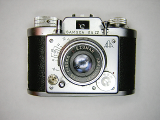
Samoca 35, 35II, 35III, 35IV
The Samoca 35 are a series of simple 35mm viewfinder cameras made
in Japan during the 1950s by Sanei Sangyo. The cameras shown here are the
simple viewfinder models. There were four different models all with the same
body, viewfinder and lens. The later models (35III and 35IV) have a slightly
different focusing lever and include a depth of field scale on the front
plate. The models 35II and 35III have a simple two blade, three speed shutter that
operates by varying the mainspring tension. These models also use the older
Kodak style flash connector. The model IV has a nice five speed shutter utilizing
a retard escapement and also has been updated to the standard PC flash connector.
The lens on these cameras is the 50mm f/3.5 Ezumar triplet. This is a pretty
good lens for a camera of this class.
There are several interesting features on these cameras. First is the
cocking "plunger" mounted on the left side of the front. This plunger
tensions the mainspring while simultaneously moving the film counter and
releasing the winder lock. Because this plunger releases the winder lock,
you should wind the film between cocking the shutter and taking the picture.
The pressure plate is attached to the camera body rather than the back.
A leaf spring in the back creates pressure on the plate after the back
is installed on the camera. You obviously need to insert the film under the
plate when loading the camera. The takeup spool comes out of the camera.
To rewind the film, you have to push-in and hold the cocking plunger so
that the sprocket can turn backwards without stopping.
The camera's construction is very simple. The entire shutter and lens
assembly lifts off from the front as a single unit. One thing to note is that
the body is bakelite. Care has to be taken not to apply too much force on
the screws so that you don't crack the bakelite. Otherwise, this is a very
simple camera to work on. These instructions are for the 35III and 35IV.
The 35II is almost identical. The only real difference is the focus lever.
|
|
 |
To remove the shutter from the camera, simply unscrew the four accessible
screws on the front and then lift the assembly off. Turn the shutter over
to access the shutter mechanism. Don't remove the screw in the speed setting
dial at this time.
On the 35III, the top right screw on the front was used as a post
for the return spring of the cocking plunger. This screw won't lift out
until you turn the shutter over and unhook the spring.
|
 |
To remove the lens unscrew the three screws in the focus control
ring and lift the ring off. The lens can then be unscrewed from the
camera. On the 35II, there is no focus ring. You remove the two
screws from the stop instead.
When unscrewing the lens, turn the back portion of the lens, the
part that moves the focus. This will push the lens up until it clears
the guide post and then the entire lens will begin rotating until it
unscrews. Separate the inner and outer helicoid, noting the position
where they separate.
|
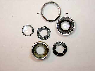 |
To disassemble the lens and diaphragm, unscrew the front lens
assembly. Then, unscrew the rear lens using a pointed spanner.
Remove the two screws in the sides of the aperture setting ring
and lift the ring off. Lift out the ring that moves the blades
and then lift the blades out. Note that there are usually two sets of
holes in the diaphragm operating ring. I have found that only one
of the two holes gives the correct maximum aperture.
|
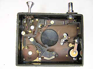 |
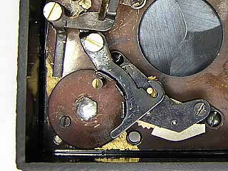
This picture shows the shutter for the 35IV. Most of the
shutter mechanism is accessible for cleaning without any disassembly.
However, the grease from the focus tends to get down onto the blades
and you may have to remove the blades for cleaning. To do this, simply
remove all the parts from inside the shutter first. The cocking
plunger unscrews and can then be lifted out. The bracket on the
right side underneath the release has to be taken out as well. This
bracket is held by two screws underneath the leatherette.
You will also need to remove the front lens and then the speed
dial from the front. The speed dial is held by a nut on the back. You
have to hold the nut with pliers while removing the screw in the
dial. With the lens and speed dial off, remove the single screw
remaining in the front cover and pull the cover off. Remove the
screws under the cover and the shutter plate will separate from
the housing.
The leatherette on this camera is so thin and brittle that I don't see anyway to
lift it off and then replace it. I ended up replacing the leatherette
with some material from a dead Konica C35. The grain pattern is almost
identical.
NOTE: In this picture the lever that moves the pin on the retard
sector gear is displaced. (This is what happens when you try to remove
the speed dial first!)
|
 |
This picture shows the speed control lever for the shutter for the 35IV after
it was put back in the correct place. The three tabs can be bent slightly
to adjust the speeds. On this shutter, I found that once it was cleaned all
the speeds were within 1/3 stop, so I left it alone.
|
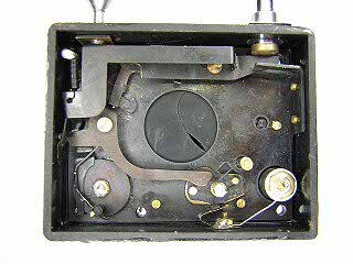 |
This picture shows shutter for the 35III. The 35II is essentially the same.
Like the shutter on the 35IV, you remove the blades by first removing all the
shutter mechanism from the back, then remove the speed setting dial and cover from
the front.
The two posts that hold the blade operating lever and blade closing spring have round
nuts on them. These screw off with pliers. Note that one of these nuts is
soldered in place, as is the nut on the back of the speed setting dial. Unsolder
them first before attempting to remove them.
Speed control on this shutter is done by varying the main spring tension. You
can bend the spring slightly to increase or decrease the speeds. On this shutter,
all the speeds were only about 4-5ms apart in speed. I was able to get them
all within 2ms of the correct speed by carefully adjusting the spring. It's a good
idea to leave this shutter sitting on the 1/25 setting when not in use. That will
help minimize loss of tension in the main spring.
|
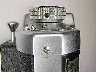 |
To remove the top cover, remove the setscrew in the rewind knob, then
hold the film cartridge fork while unscrewing the knob. Remove the screw
in the side of the top cover. Do the same thing on the right side with
the wind knob and screw.
The film counter lifts out from the top. Watch for the spring washer between
the film counter dial and the rewind knob.
Lift up the top cover and then tilt it forward to slide off of the
lever that extends through the front of the cover.
There is a light seal along the top of the back. On both of the
cameras I worked on, the glue from this seal had run into the top
cover making the cover difficult to remove. Use a solvent here if
the top cover is difficult to lift off.
|
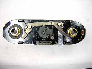 |
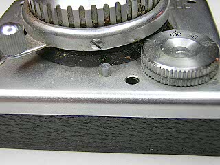
This image shows the film counter and winder lock mechanism with
the top cover off. (Winder is on the left.) The film stop is operated by the single film sprocket.
Note the film counter ratchet pawl sitting against the feed spool shaft tube.
When reinstalling the film counter gear, you need to hold the ratchet pawl
back out of the way. I found the best way to do this is to take a loop of
thread and hook it over the pawl then feed the thread out through the slot
where the film counter lever passes through the top cover. You can then
pull the pawl back while setting the film counter dial in place. Once the
dial is in place, pull the thread out.
When reinstalling the wind knob, you have to push in on the film counter
lever and move the film sprocket slightly so that the interlock is held back.
|
Notes
To adjust the lens focus, remove the three screws and focus ring. Turn
the lens until it is sharp at infinity and then reinstall the focus ring
against the infinity stop.
If you need to remove the pressure plate, remove the two screws at the
bottom of the film gate and the two screws at the top. The entire film
gate lifts off the body.
The two chrome pieces on the sides are purely decorative. These
pieces can be removed if needed by simply removing the screws holding them in place.
|