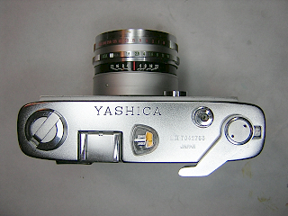
Yashica Lynx 5000
The Yashica Lynx series of cameras are fixed lens, leaf shutter rangefinder cameras
made in the 1960s. These cameras are well made, all metal body cameras with excellent lenses
and are often underpriced for their performance. The Lynx models were the 1000, 5000, 5000e, 14 and 14e.
All of these cameras have built-in meters, full manual settings,
and very good Yashinon lenses. The 1000, 5000, and 5000e have a f/1.8 Yashinon lens. The 14 and 14e have an excellent, very fast f/1.4 lens.
The Yashica "J" camera is very similar to the Lynx 1000, but has a simpler shutter, 1:2.8 lens, and no built-in meter.
The first camera, the Lynx 1000, had a selenium cell
to directly drive a galvonometer. In the Lynx 5000 the selenium cell was replaced with a CDS cell and
requires a 625 mercury battery to operate. (Although mercury batteries are no longer available, I have
gotten good results with zinc-air hearing aid batteries.)
The Lynx 14 was an improved version of the 5000 that used an f/1.4 lens.
Later in the 5000e, the galvonometer was replaced with an electronic metering system that
displays over and under indicators in the viewfinder instead of the meter needle. The Lynx 14e has the
same f/1.4 lens as on the Lynx 14 but uses the two display lights as on the 5000e. The 14e and 5000e use
two 640 size batteries instead of the 625 battery. On these two models, alkaline batteries will give good exposures.
Joe Wolf offers an adapter that replaces the hard to find 640 batteries.
In all cameras, the exposure setting
is done manually. To set an exposure, you press a switch on the front to turn on the meter and then adjust the
shutter speed and/or aperture until a proper exposure is indicated. Note: on the 1000 you don't have a switch
to press because of the seleium cell.
The 1000 and 5000 have an interesting feature that works as a kind of mechanical shutter priority
exposure mode. When you turn the shutter speed ring, the aperture setting ring turns in step
with it. Thus, reciprocity is maintained while changing the speed setting. To actually change
the exposure setting, you turn just the aperture ring. This can take some getting used to,
but works relatively well.
One unique feature of the Lynx metering system, and used on all the models, is the carbon strip
resistor located in the lens barrel. Most meters on cameras of this era use some type of variable size hole
over the CDS cell to vary the amount of light seen by the cell. The Lynx system works instead by varying the
resistance of the circuit using a series of pick-up brushes mounted on the shutter base. As the shutter speed,
aperture ring or ASA setting is changed, the pick-up brush is moved along the resistive strip, thus varying
the resistance of the circuit and the amount of current seen by the meter. Because this carbon strip
can wear, the meters in these cameras can be off by 1-2 stops. The CDS cell on the Lynx is mounted on
the camera body instead of in the lens barrel. This means that if you put a filter on the lens, you
need to make a manual adjustment to the exposure. Also be aware that the CDS cell can pick up light
reflected off the lens barrel. When shooting in bright sunlight, this can result in underexposure if you
blindly follow the built-in meter. In the end you always have to use your judgement in addition to a
built-in meter!
A very common problem on these cameras is an inoperative diaphragm. Because the aperture setting control
is in the middle of the lens barrel, the control has to be linked to the diaphragm with a lever. This lever
is easily bent and can pop out of the slot it fits into. Usually, an inoperative diaphragm can be fixed by
simply removing the front lens and control rings, bending the lever back in place, and putting the controls
back on the camera.
The camera shown here had the typical problems of inaccurate shutter, dirty and out of adjustment rangefinder,
and corroded battery lead wire. I later found out that the self-timer was ruined and had to be replaced as well.
It also had a badly damaged aperture control that needed to be replaced. Finally, all
the grease in the focus had dried out (or more likely flushed out by an improper cleaning).
As a result, the camera had to be almost completely disassembled. The camera was however in very nice
cosmetic condition so I felt it was worth fixing rather than just using for parts.
Fortunately, the Lynx is a relatively easy design to work on. Just try doing something
like this on a Canonet some time and you really appreciate the simplicity of this camera's
design!
For additional information, check out Joe Wolf's excellent Yashica site --
The Yashica Guy
 |
To remove the top cover, open the back and hold the rewind fork while unscrewing the rewind knob.
Watch for a washer underneath the knob.
Unscrew the pinface screw in the wind lever and then lift off the spring washer,
wind lever, cam, and shim.
Remove the screws in the side of the top cover and lift the cover off. The screw
in the back is only a rangefinder adjustment cover and can remain in place.
The release button has a pin inside it that may fall out. Often, this pin
has a small amount of grease on it that will cause it to stay in place.
Turn the top cover over and you see a strip of light seal foam next to
the meter display window. Usually this foam is rotten and needs to be replaced.
The accessory shoe cover is removed by lifting up the front edge and sliding
the cover back.
|
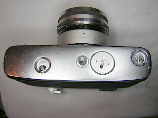 |
The bottom cover is held by two screws. The battery cover can remain attached.
When removing the cover, watch for
the door latch release lever. This lever has a spring attached to it and will
swing out of place when the cover is removed. There is a washer on the button
and if you are not careful the washer will fly off as the spring pushes the
lever out of place.
|
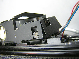 |
This image shows the rangefinder adjustment screws. The screw in the back
adjusts the horizontal matching. The screw on the side moves the mirror to adjust the
vertical matching. There are often shims behind the mirror to adjust for variations
in mirror width. If you install a new mirror, you may need to remove or add shims
to get the vertical matching correct. You may also find it necessary to slightly
bend the bracket holding the mirror to get it flush against the adjustment screw.
The black paper cover over the rangefinder is glued in place. Just slide a
knife blade along the edge to remove the paper and give access to the lenses
for cleaning.
|
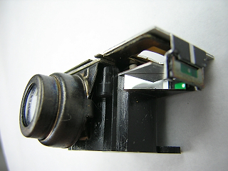 |
This image is a closeup of the meter. Note the small mirror sitting at
an angle behind the meter needle. This mirror provides illumination for
the meter needle and causes the needle position to show in the viewfinder.
Often this mirror is missing. You can replace the mirror with anything shiny
enough to reflect light into the viewfinder. I have used both aluminum foil
and stainless steel shim material to do this and both work fine.
The green colored glass is painted. It is not a good idea to try
and clean this as the paint will easily rub off.
|
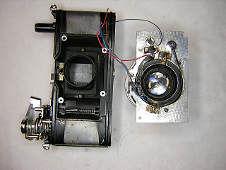 |
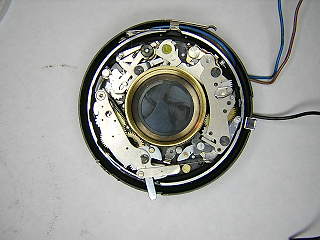
To remove the shutter from the camera, first unsolder the wires at
the meter, making a drawing of the position of each wire. I find it difficult
to get a soldering iron in to work on the meter, so I usually just remove
the meter first. The meter is held by two screws at the back.
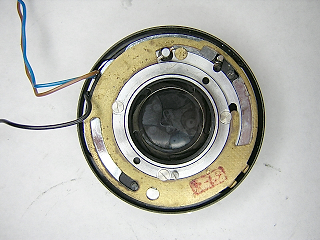
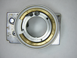
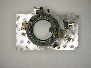
Peel back the leatherette on the front to expose the four screws. Remove
the screws and then carefully lift the mounting plate off the camera. The battery
lead wire is connected to the switch on the front. Unsolder the black lead wire
and the entire shutter and lens is then free from the camera. The red wire
can remain attached.
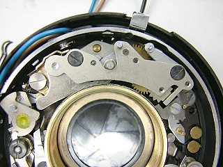
Back out the screw on the wiring bracket to get the wires free.and then
unsolder the flash connector wire.
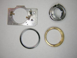
Unscrew the rear lens and then unscrew the shutter retaining ring and the
shutter will lift out of the mounting plate. You need to pull the wires through
as you lift the shutter off. There is a light seal around the rear lens. This will
almost always be rotten and need to be replaced.
On every Lynx I've worked on, the shutter retaining ring was screwed in
extremely tight. Apparently these rings are installed before the paint is
set and are thus "glued" in place by the paint. Try running some laquer thinner
or acetone around the ring to loosen the adhesion.
This picture shows the rangefinder removed. I did this to make
repairs on the rangefinder. Normally, the rangefinder can remain in place.
|
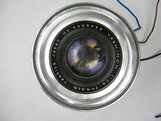 |
To disassemble the shutter, start by unscrewing the front lens. Set
a friction tool against the inner chrome ring and turn it. The lens
and ring will come out as a unit.
|
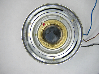 |
The filter ring unscrews as well. If you are not going to disassemble
the speed and aperture control, the filter ring can remain in place.
|
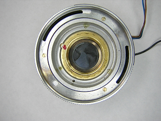 |
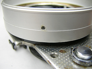
Turn the lock screw 1/2 turn until the flat side faces towards the center
then unscrew the serrated retaining ring. The controls can then be lifted
off the shutter. When lifting the controls off, be careful not to bend
the wiper springs attached to the shutter base.
The three screws visible from the front hold the speed control
ring to the resistor ring. Don't remove these screws at this point.
These screws can be loosend and the resistor
ring turned slightly to make adjustment to the meter. It's a good idea
to mark the position of the resistor ring if you intend to disassemble
these pieces.
|
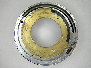 |
To disassemble the aperture, turn the shutter over and remove the
three screws in the brass plate. Note the position of the gap
in the plate relative to the hole in the black inner tube.
This picture shows the plate at the B position.
Lift the plate off and the interior aluminum tube will also come out from the front.
These three screws are slightly different in length than the
three screws that hold the shutter speed ring in place. The first Lynx
I worked on I got the screws swapped. When that happens, the lens
will not screw all the way in. It probably took me a day to figure
out what I did wrong, so make sure not to mix up the screws.
Extending out of the aperture ring is a lever that extends back
through the shutter to operate the diaphragm. Although difficult to
see in this picture due to the angle, this lever is badly bent on this camera.
Most Lynx cameras have this problem to some extent.
The lever is soft metal and easily bent so you can carefully
bend it back straight. However, the lever will often break
loose from its studs in the aperture control ring. If this happens,
just reattach the lever with super glue after bending it straight.
On this camera, the lever
was so badly bent that the aperture control ring was damaged. You
may have to straighten this ring as well. I had a spare from a junk camera,
so I just replaced the ring rather than try to bend it back straight.
|
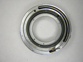 |
The aperture ring is held in place by two flat metal springs (see next picture)
and simply lifts off.
|
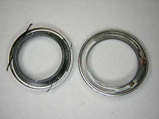 |
This picture shows the aperture ring separated from the shutter speed ring.
Note the two flat springs riveted to the black inner tube.
The purpose of these springs is to move the aperture ring when the shutter speed
is changed so that the exposure value remains constant. The tension of these
springs has to be strong enough to overcome the resistance of the diaphragm but
light enough to slip when the diaphragm reaches the end of its travel. This
little feature is what causes so much problem with the diaphragm control lever.
These two pieces are easy to take apart, but can be quite difficult to reassemble.
I'm always tempted to just break off the springs.
Turn the shutter speed ring back over and remove the screws from the front. The
pieces will then separate. Look at the inside of the resistor ring and you see
a strip of carbon that provides the resistor for metering. This strip will sometimes
develop dead spots and can also come loose. I avoid trying to clean this strip
since doing so tends to remove some of the carbon. You need the appropriate
electrical cleaner to clean this properly.
|
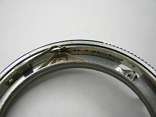 |
This picture is a closeup of the ASA click stop and ASA wiper inside the
aperture ring. To remove the ASA ring, pull back the click stop spring and
remove the steel ball. Lift the ASA ring out and then remove the click stop
spring. Be very careful around the wiper. It is very thin metal and easily
bent. If you bend it, straighten it back before reassembly. Check for corrosion
on this wiper and clean it if needed.
This wiper is key to the metering system. The battery + side is electrically
connected to this wiper through the battery cover, camera body, front
mounting plate and shutter housing. As the aperture ring is rotated, this
wiper moves along the resistor strip and varies the amount of voltage
that is picked up by the two wipers attached to the shutter housing.
Rotating the shutter speed ring moves the resistor past the two
wipers also.
|
 |
This picture shows the shutter mechanism. The Copal SV shutter is
very similar to the Copal MXV shutter.
Note the two wipers at the top of the shutter base. These wipers
have to slide into slots in the shutter speed control ring during
reassembly. Be careful not to bend them, and clean them if they
show signs of corrosion.
|
 |
This picture is a closeup of the escapement retard. Unlike the
MXV this escapement only has two screws holding it to the base. You
remove the screw at the top in the cover and the screw at the base
next to the pallet. There are shims underneath the assembly.
Usually a slow shutter indicates that there is dried lubricant
and dirt in the mechanism. You clean and lubricate it and the shutter comes back
to proper speed. On this shutter, the slow speeds were too fast. Although it
may sound strange, that is also usually caused by dirt and dried lubricant.
Look at how the pallet sits on a lever that is held back by a stud on the
blade operating ring. When the shutter fires and the speed cam is set to
the slow speed range, this lever has to swing into place fast enough
so that the pallet is engaged before the mainspring unwinds past the
retard. If this lever is sticking, the pallet won't move into
place and the shutter will run fast at the slow speed settings.
A complete cleaning solved the problem and the shutter now runs
perfectly at one second.
|
 |
From the back of the shutter you see the diaphragm control plate.
There is a slot in the edge of this plate that must mate with the
lever attached to the aperture control ring. The slot is at the
lower right in this picture. This slot can get bent
so that the lever will not sit properly inside it. Bend the small
tabs if needed so that the lever does not pop out of the slot.
In order to separate the shutter halves, remove the three screws
holding this plate and then lift the plate off. Remove the screw
holding the M/X selector. After that, disassembly
is essentially the same as for the MXV shutter.
|
 |
To disassemble the focus helicoid, start by removing the two screws
in the focus knob then lift the knob and focus scale off.
This picture shows the focus ring rotated against the infinity stop.
You may want to mark the infinity position of the brass ring before
disassembling further.
|
 |
Back out the setscrews in the side of the focus control ring
and lift the ring off.
At this point you should carefully measure the height of the brass
ring above the base. This will help determine the proper location during
reassembly of the helicoid.
|
 |
Turn the front plate over and remove the rangefinder coupling bracket
and the three screws holding the helicoid to the front plate. The
entire assembly will then separate from the front plate.
Look at the shutter release lever. There is an eccentric post
on the end of the lever. You can turn this post with a screwdriver
to change the position of the shutter release.
The guides can remain attached to the front plate.
This picture shows a bracket at the bottom where the
flash wire goes. This was put there inadvertently and is not supposed to be there.
|
 |
Unscrew the helicoid from the black outer ring and then separate
the inner and outer helicoid pieces. Count the number of turns and
note the position where each of the rings separates. It will make
it easier to reset the focus after reassembly if you reposition
the pieces at their original position.
|
Notes
To adjust focus, remove the focus knob and scale.
Turn the focus ring until the image is sharp at infinity.
Back out the setscrews around the focus ring and rotate the
ring clockwise against the infinity stop. Re-tighten the
setscrews and reinstall the knob and scale. When installing
the scale, put the screws in the knob in slightly loose, then
position the scale so that the infinity symbol is properly
aligned. Slide along the scale to remove any slack and then
tighten the focus knob screws.
To adjust the rangefinder horizontal alignment, remove the
cover screw in the back of the top cover. Insert a screwdriver
and turn the eccentric until the images align. Note that this
is not a screw and does not tighten. The eccentric moves a bracket
back and forth to turn the pivoting mirror. Vertical alignment can
only be adjusted with the top cover removed. Turn the screw on
the back of the mirror until the vertical alignment is correct.
It is possible to make slight adjustement of the meter alghough I've
never had to do it. Unscrew the front lens and filter ring
and then loosen the three brass screws. Slide the resistor
ring back and forth until the meter reads correctly.
If the shutter release button does not fire the shutter,
you can rotate the eccentric located on the release lever attached
to the helicoid. Obviously this can only be done after removing
the front panel. Small adjustments can be made by removing
the bottom cover and turning the release shaft with a screwdriver.
When making this adjustment, check to make sure that the
winder lock releases at the same time as the shutter. Press
the shutter button slowly and listen for a soft click sound.
If you hear the click before the shutter releases, the
winder lock is resetting too early. If the shutter fires before
the winder unlocks, the winder lock is resetting too late. Turn
the screw in the release shaft until the two actions happen
simultaneously.
|