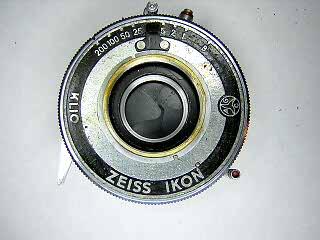
Klio (Prontor-S/Prontor-II) Shutter
The Klio shutter is a Zeis-Icon brand for a Prontor-S shutter.The Prontor-S is the full range shutter that later is modified into the Prontor-SV and Prontor-SVS shutter. Several Gauthier shutters such as the Pronto, Vario, and Vero are simplified versions of the Prontor-S. The older Prontor-II shutter is nearly identical to the Prontor-S. On some Prontor-II shutters the escapement mechanism is held to the shutter base with screws from the rear. You have to separate the shutter halves to remove the escapement.
The Prontor-S uses a standard escapement retard and has flash synchronization (which is indicated by the "S" designation.) Disassembly is typical for Gauthier shutters. The main difference between the Prontor-S and the later SVS model is the self-timer. Note: the Gauthier parts list calls the self timer the "delayed action device."
This shutter is from a Zeis-Ikon Ikonta B. This shutter was in overall working condition when I got it. However the spring on the flash contact was "fried" and broke off. I replaced the spring with one from another shutter, cleaned the escapment and was done. The slow speeds were a little slow and I was attempting to try to put a very small amount of oil in the pallet before cleaning it again. Unfortunately, I tipped over the bottle of oil and flooded the shutter. This required me to completely disassemble the shutter, including the diaphragm, to clean out all the oil. Interestingly, when everything was reassembled, the speeds ran correctly. This is something I have encountered before. The blades may look clean if someone has flushed the shutter to clean it. However a small amount of contaminants can get trapped underneath the blade drive ring. By doing a complete disassembly and cleaning, the shutter returned to proper operation. This is something to remember. Flush cleaning may not always get the shutter completely clean.
Although I did it accidently on this shutter, soaking shutter parts in oil is another little trick I have used on many shutters. Old, dried grease will not always come loose just from soaking in solvent. The oil will soften the grease and make it easier to flush out.
 |
Remove the lens cells from the front and rear. Typically the inifinity stop is performed by a screw-in post on the side of the focus ring. Remove the stop post and the front lens cell will unscrew. The center lens can then be unscrewed from the shutter.
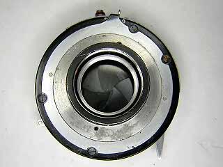
Unscrew the slotted retaining ring around the center of the lens opening and lift off the faceplate.
|
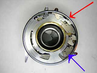 |
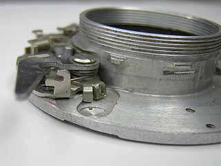
This picture shows the speed setting cam set for the top speed. The arrow at the right-top points to the location of the speed setting pin. This pin can sometimes get bent and cause problems at the higher speeds. As you rotate the cam, the pin should remain against the outer edge of the case until the mainspring is tensioned. When the mainspring is tensioned, the pin should swing freely in so that it rests against the cam. If the pin does not move at all, it is most likely contaminated with grease or oil and a cleaning will restore it to correct operation. If the pin does not remain against the case when the shutter is not cocked, then it is probably bent and must be gently bent back to position. Always clean the shutter first before attempting to correct problems by bending parts.
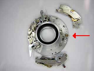
The arrow at the lower right points to a small part that prevents the self timer from being used when the speed is set to B. This part falls out. Remove it before continuing with further disassembly.
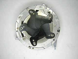
The shutter speed cam lifts off. Clean then lightly lubricate the cam with grease where it rubs against the faceplate and shutter case.
|
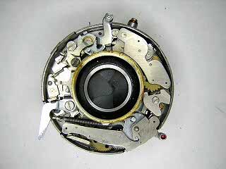 |
This picture shows the entire mechanism. The release trigger and B lever are on the left. The escapement mechanism is on the right and the mainspring is at the top.
To remove the retard mechanism, tension the mainspring so that the lever on the sector gear swings out toward the main cam. The screw holding the top of the assembly is now exposed. Remove the screw at the top and the screw at the bottom, then lift the assembly out of the shutter. Pull the sector gear out slightly while lifting in order to clear the lip of the lens opening.
Unhook and remove the blade closing spring located at the bottom of the escapement mechanism.
|
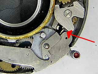 |
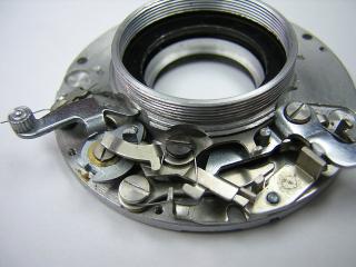
This picture shows a closeup view of the area between the escapement and the self-timer. There are two tabs here that can become bent if someone has forced the shutter when it was jammed. The lower tab must slide into the opening of the self-timer lever. If the shutter hangs, check to see if this tab is bent such that it stops against the self timer cam. Bend the tab back slightly so that it clears the opening on the cam.
The tab above is used to hold the pallet back during cocking and when the speed is set to the high range. If this tab is bent it may not sit properly against the speed cam and will cause the escapment to be positioned too close or too far away during operation of the shutter.
Note that the pallet is held on by a screw. If the shutter is slow in the slow speed range, remove this screw and lift the pallet off. Clean the inside of hole in the pallet with a toothpick dampened with solvent.
|
 |
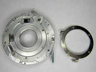
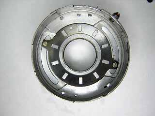
Turn the shutter over. There are four screws holding the two halves of the shutter together. To access the screws, turn the aperture ring until the cut-outs match the screws.
When removing the screws note that one screw is longer. This is the post that holds the blade closing spring.
|
 |
Slowly pull the shutter halves apart trying not to disturb the blades. For shutters with the flash contact mounted on the case, as here, rotate the base slightly and then tilt until the inner base clears the flash contact.
Note the direction of the shutter blades. On reassembly, the blades must be installed in a clockwise order so that they will slide easily over each other.
Never touch the blades with your fingers. Carefully lift the blades off with tweezers.
|
 |
This image shows the front half of the shutter. I have reinstalled the blade closing spring to show where it is located. The short end of this spring hooks onto one of the case screws.
The self timer simply sits on a post and pivots back and forth slightly. There are no screws holding it in place. When cocked, the tension on the self timer spring causes the whole assembly to swing in towards the center of the shutter where it latches onto the end of the release lever.
To remove the self timer, unhook the coiled spring from the right side and then rotate the setting lever slightly so that the cam clears the lip on the lens opening. The self timer can be removed without separating the shutter halves, but it is easier to do once the shutter is separated.
|
 |
This is a view of the release and B levers. I soaked the shutter base with these parts attached in solvent to clean them. If you need to disassemble these parts, see my article on the Vero shutter.
The cocking lever is held by a single screw. Remove that screw to remove the lever, blade operating hook, and mainspring. There is a tiny spring underneath that pushes the hook against the tab on the blade operating ring. Make sure that spring is properly engaged. If the spring is knocked loose or broken, the shutter will operate but the blades will not open and close reliably. Sometimes the hook will engage and sometimes not. This can be very confusing.
There is a tab that extends down from the cocking lever and is what engages the escapment mechanism. This tab can get bent so that the lever strikes the retard to early or late and throws the speed range off. Check to make sure this tab strikes the retard at the point where the blades are fully opened. Bend it back into place if it is bent.
|
 |
This is a view of the end of the release lever. Note that there are two springs here. One spring is on top and pushes the release lever back into position. The bottom spring goes through the hole in the self-timer latch. When the self timer is cocked, this latch holds it until the shutter is released. The self timer then swings away and start running.
|
 |
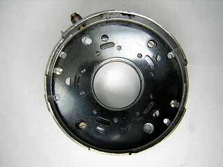
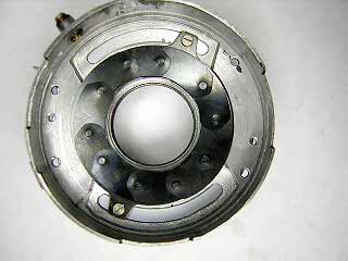
To remove the blade operating ring, turn the shutter base over and remove the five screws and washers holding the ring. Contaminants can get trapped inbetween this ring and the shutter base. Often the only way to clean it is to remove the ring and then wipe off the ring and base with a paper towel dampened with solvent.
On reassembly, the post on the blade operating ring must engage the hook in the blade operating lever. Pull the blade operating lever back when inserting the blade ring and it should drop into place.
The screw on the right side of the base holds the plate that the release lever sits on. On some versions of this shutter, that plate contains the cable release socket.
|
 |
If you rotate the diaphragm to the maximum aperture you should see two screws accessible through the cover plate. These screws hold the aperture setting ring on. You can remove these two screws and lift off the setting ring for cleaning without disassembly of the diaphragm.
The two screws on the top of the cover hold the cover in place. Remove these two screws and lift the cover off to gain access to the diaphragm blades. Because this type of diaphragm is difficult to reassemble, normally the diaphragm is not disassembled unless it has a damaged blade or it will not flush clean.
|
 |
This picture shows the diaphragm blades. Lift the blades out. For information on assembly of this type of diaphragm, see my aritcle on leaf shutter diaphragm mechanisms.
|
 |
With the diaphragm blades removed you can remove the control ring underneath for cleaning.
|
Notes
AGC shutters are designed to run dry. Only add a tiny amount of oil to the pallet if it will not run properly after cleaning.
Lubricate the speed setting cam plate where it rubs against the case and faceplate.
|