The Vero shutter is a simplified version of the AGC Prontor shutter.
The shutter uses a simple inertia gear train instead of an escapement to retard the main spring.
Only X synch is provided and there is no self timer.
Vero shutters were used on a variety of German manufactured consumer grade viewfinder and rangefinder cameras.
This shutter is from an Iloca Rapid A.
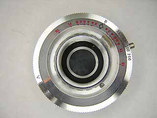 |
Remove the lens cells from the front and rear. Turn the lock screw until the flat side
is towards the center of the shutter. Unscrew the scalloped retaining nut that is around
the lens openeing. Lift off the faceplate and speed setting cam.
|
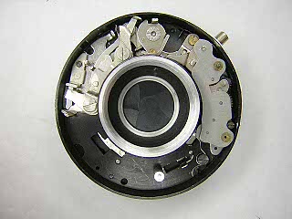 |
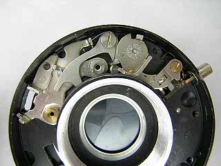
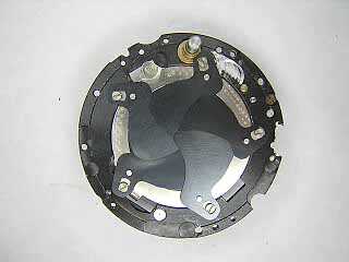
This picture shows the entire mechanism. The release trigger and B lever are on the left.
The inertia retard assembly is on the right and the mainspring is at the top.
|
 |
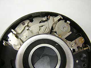
To remove the inertia retard assembly, wind the mainspring so that the lever on the
sector gear swings out toward the main cam. The screw holding the top of the
assembly is now exposed. Remove the screw at the top and the screw at the bottom,
then lift the assembly out of the shutter. Pull the sector gear out slightly while
lifting in order to clear the lip of the lens opening.
Unhook and remove the blade closing spring located at the bottom of the inertia retard assembly.
|
 |
Unhook and remove the spring on the B lever. Remove the screw in the B lever and then lift the lever off.
|
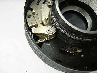 |
Unhook the spring on the trigger then remove the screw in the trigger and lift the trigger and spring out.
|
 |
Unhook and remove the spring on the latch then remove the screw in the latch and lift the latch off.
Underneath the latch there is a brass bushing. Note how the spring that tensions the
blade operating lever sits against this bushing. On reassembly, the spring must be
repositioned before installing the latch lever and screw.
|
 |
Remove the screw from the flash contact lever and lift off the lever and contact underneath.
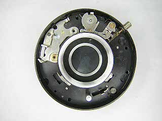
The plate on the left side of the shutter cannot be removed until the inner and outer
bases are separated. The small part sitting on top is secured by a screw from the back
and must be removed first. On older Prontor shutters, this small part is the cable release socket.
|
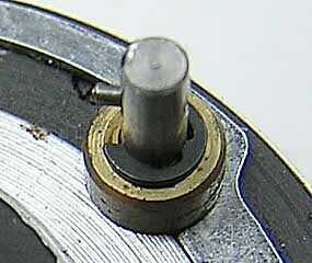 |
Turn the shutter over and examine the wind stem. On this shutter the stem is held
in place by a tapered pin, e-clip and collar. The tapered pin engages the winder pinion to cock the shutter.
Remove the pin, clip and collar from the wind stem.
On some cameras, there is a pinion mounted directly on the wind stem with a set screw.
|
 |
There are four screws holding the two halves of the shutter together. To access the screws,
turn the aperture ring until the cut-outs match the screws. It may be necessary, as on this
shutter, to remove some screws at one position, turn the ring and remove the remaining screw(s).
When removing the screws note that one screw is longer. This is the post that holds
the blade closing spring.
|
 |
Slowly pull the shutter halves apart trying not to disturb the blades. For shutters with
the flash contact mounted on the case, as here, rotate the base slightly and then tilt until
the inner base clears the flash contact.
Note the orientation and order of the shutter blades. On reassembly, the blades must
be installed in the correct order so that they will slide easily over each other.
On this shutter the blades are installed in a counter-clockwise order.
Never touch the blades with your fingers. Carefully lift the blades off with tweezers.
|
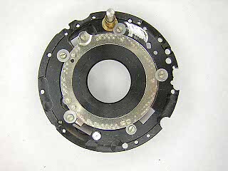 |
Remove the five screws and washers then lift the blade operating ring off.
On reassembly, the post on the blade operating ring must engage the hook in
the blade operating lever. Pull the blade operating lever back when inserting
the blade ring and it should drop into place.
At this point it is possible to remove the plate on the front if desired.
Also, the main spring and cam can be removed if needed. Normally, the main spring can
stay in place. On this shutter the main spring is relatively weak and is easy to
remove and reinstall. Be sure to note how the spring sits in the base before removing
the spring.
|
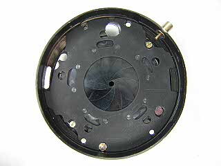 |
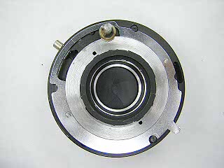
This picture shows the diaphragm assembly. Normally, this is cleaned by soaking in solvent
and blowing out with compressed air. The two small screws hold the aperture setting ring
and can be removed to lift the ring off the back of the shutter. The larger screws on the front
towards the edge hold the cover plate in place. To access the blades for replacement, remove the screws and
lift the cover off. The ten blade diaphragms can be tedious to reassemble. You have to place
all but three of the blades in first, then slip the last blades in underneath so that
they overlap properly.
|
Because this shutter lacks an escapement, there is no easy way to adjust the speeds.
It is possible to file or spread the speed cam for precise speed settings. However, if
the shutter is clean and the main spring has not become greatly weakened,
the speeds should be fairly accurate. It's best to just measure the speeds and then
make appropriate exposure adjustments by altering the aperture.
AGC shutters are designed to run dry. Lubricate the speed setting cam plate where
it rubs against the case and faceplate.