Some of these pictures were taken during disassembly and some after re-assembly.
You can see how dirty the chrome plating was. I cleaned the chrome parts by scrubbing
with an old toothbrush and soap and water then polished with
Flitz polish.
If you look closely, you will also notice that the pictures don't show exactly the
same sequence of disassembly as the text. Becuase I don't always have a factory
repair manual, many of these repairs have to be done on a "learn-as-you-go trial-and-error"
process. After I get the thing apart, I usually realize there was a better way to
do it.
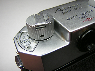 |
Remove the set screw in the rewind knob, then open the back and hold the rewind fork while unscrewing the rewind knob.
|
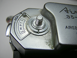 |
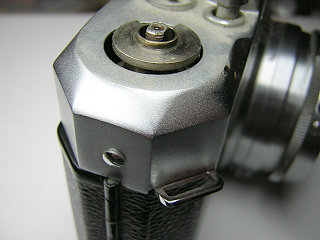
Underneath the rewind knob is a slotted retaining nut. Remove the nut.
|
 |
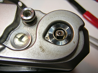
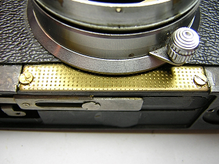
Use a friction tool to remove the screw-in cover over the wind lever.
|
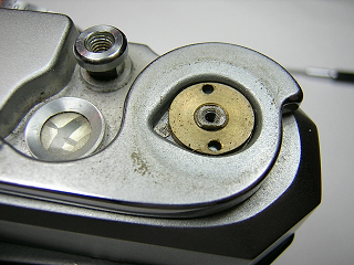 |
Underneath the wind lever is a brass screw with two
holes in it. Use a spanner with pointed tips to remove the screw.
|
 |
Lift out the spring washer and the wind lever.
|
 |
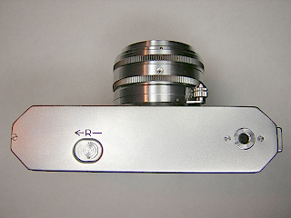
Remove the screw in the winder side of the top cover and then lift the top cover off.
|
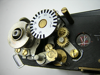 |
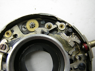
This image shows the winder and film counter gears.
|
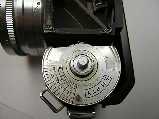 |
With the top cover off, you can remove the film reminder assembly for cleaning.
|
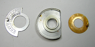 |
The film reminder assembly consists of the three pieces shown here.
|
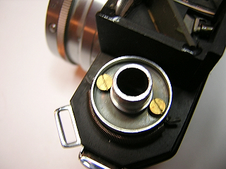 |
To access the rewind shaft spring, remove the screws around the rewind shaft and lift the bushing off.
In this picture I've already pulled the rewind shaft out.
|
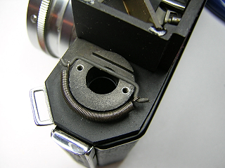 |
Pull back on the spring and lift it off.
|
 |
The rangefinder is held on by three screws. Two screws are visible behind the beamsplitter and the center mirror.
The third screw is located in the hole at the front. Remove all three screws and the rangefinder will lift off.
It's not necessary to remove the rangefinder to work on the shutter. I removed it because some of the
lenses had come loose and I needed to reglue them. It was easier to do with the rangefinder off the camera.
|
 |
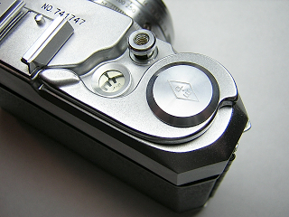
Remove the screws in the bottom. Unscrew the rewind release knob using a small spanner or friction tool.
Lift the bottom cover off.
|
 |
The shutter and focus assembly is held to the front panel by four screws. Pull up the front leatherette
and remove the two screws at the bottom.
The leatherette used on this camera is very brittle. Heat it with a hair dryer to soften before attempting
to remove it. Even when softened the leatherette is very easy to break. Slide a knife blade underneath to
separate the leatherette from the camera. Try not to lift up as you do this.
|
 |
Remove the two screws at the top and lift the assembly off the camera.
|
 |
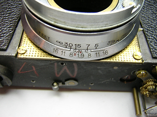
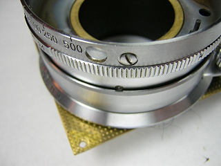
Unscrew the front lens from the shutter by turning the filter ring. There is a setscrew that
holds the filter ring against the front lens assembly. If you separate the filter ring from
the lens, you will move the aperture indicator. So, it's best to leave these two pieces together.
Lift off the LV scale and aperture ring. The large spring held by two screws can remain attached.
|
 |
Remove the three brass screws and lift off the shutter speed setting ring.
|
 |
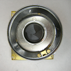
Turn the shutter over and remove the rear lens and retaining ring from the shutter. The shutter
will then lift out of the base. The cocking and release levers are under the shutter (see next picture) and are held
in place by the shutter. They will fall out with the shutter.
|
 |
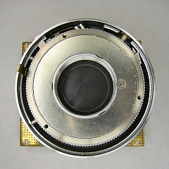
This image shows the cocking and release levers in place. Note how each mates with the sector gear and wind pinion.
There is a brass spacer ring with a flange separating the two levers. One side of the ring is slightly thicker and
needs to go towards the back of the camera. If the rings don't move freely, you have probably installed this ring
backwards.
|
 |
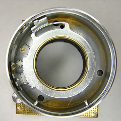
This picture shows the release lever with the cocking lever removed.
|
 |
The shutter speed scale is held in place with screws around the outside. Remove the screws and lift the
scale off.
On reassembly, I found it was easier to put the shutter back on first, and then reinstall this piece.
Remove the synch selector control ring.
|
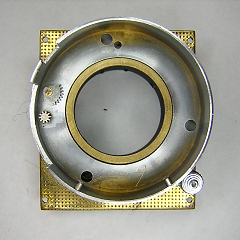 |
Before removing the next ring, turn the shutter over and note the gears and spacers around these two shafts.
(See next two pictures.)
Turn the focus to the near focus position to uncover the setscrews for the next ring.
Back out the setscrews around the sides and lift the ring off.
|
 |
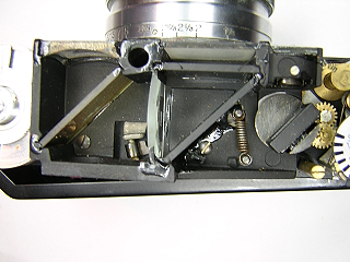
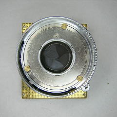
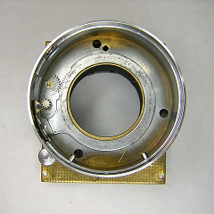
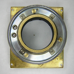
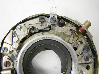
This picture shows the shutter plate from the back before the wind and release gears are removed.
At the top right you see a plate that holds the wind pinion and release gear. The plate
has some play in it and when reinstalling it you need to move it back and forth until
the winding gears all turn smoothly.
When reinstalling the shutter on the camera, the pinion at the bottom must engage the
winding rack at the bottom of the camera. The gear on the trigger shaft must mate with the
gear the turns the release.
|
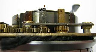 |
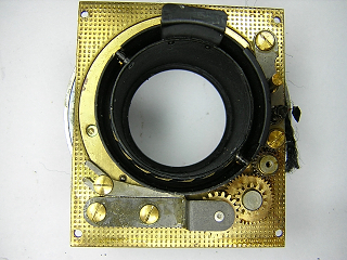
This picture shows the wind and release gears from the side. Note the spacers above
and below the gears. If you disassemble these, you need to make sure the spacers are replaced
exactly as they were. Otherwise the gears will not mesh correctly.
|
 |
Turn the focus to the infinity position and mark the position, then back out the setscrews
and remove the focus control ring.
|
 |
Remove the three brass screws and lift off the depth of field scale.
|
 |
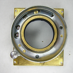
The helicoid is held to the front plate with four screws.
I did not disassemble the helicoid. It appears that to disassemble the helicoid you remove the two guide screws from the back and then unscrew the helicoid pieces.
|
 |
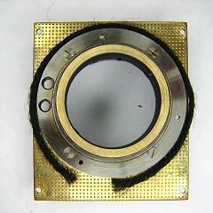
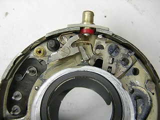
This is a closeup of the retard for the flash synchronization. Note all the grease in this shutter.
It's little wonder that the shutter wasn't working!
Remove the screw in the selector lever and lift the lever off. Remove the two screws in the cover
and lift the cover off.
The triangular shaped piece at the left is used to adjust the position of the release catch.
|
 |
Remove the gears.
|
 |
The spring for the sector gear is underneath as shown here.
|
To adjust the focus, set the focus correctly at inifinity, loosen the set screws in the
focus control ring and turn the ring to the infinity position. Re-tighten the screws.
To adjust the horizontal matching on the rangefinder, open the back and remove the screw at the top
of the film gate, insert a small screwdriver into the hole and turn the adjustment screw
until the images align. Vertical alignment is adjusted using the screw on the back
of the pivoting mirror.