[Printable Page] [RSS 2.0] [Login] |
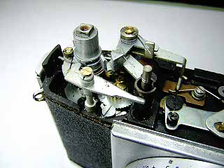
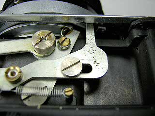
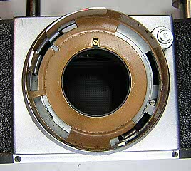
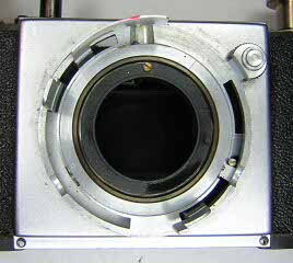
NotesFocus AdjustmentTo adjust the focus, turn the focus ring until the lens is focused at infinity. Backout the set screws in the focus scale and lift the scale up to expose the screws in the focus ring. Back out the screws in the focus ring and turn the focus ring against the infinity stop. Retighten the screws on each ring. Make sure the focus scale is sitting on the infinity mark.Rangefinder AdjustmentTo adjust horizontal alignment, open the back and remove the cover screw at the top of the film gate. Set the lens to infinity then nsert a small flat blade screwdriver into the hole and turn the adjustment screw until the rangefinder images are aligned. Replace the cover screw. To ajust the vertical alignment, pry off the cover plate on the accessory shoe to get access to the adjustment screw. The vertical alignment on my camera did not need to be adjusted. It appears that you turn the small screw to move the bracket on the mirror. It may be necessary to loosen the large screw first. There is also a screw on the back of the mirror that may have an effect on mirror position as well. Since my camera did not need to be adjusted, I did not determine which of these needs to be adjusted. |
Links: |