|
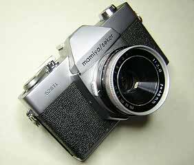
The Mamiya 528TL is a fixed lens, leaf shutter SLR sold by Mamiya in the late 1960s.
The lens is a simple front cell focusing triplet with maximum aperture of f/2.8.
The shutter is a variant of the Copal shutter with speeds from 1/500 to 1/15 plus B with X flash synch only.
The exposure control is either manual setting or shutter priority auto exposure.
The body is molded plastic with plated brass top and bottom. The metering system uses a single
676 size mercury cell. The battery is only needed for operation of the auto-exposure
system and meter. The camera will still function as a manual exposure camera without a battery.
(Zinc-air hearing aid batteries work as a suitable replacement.)
It's difficult to understand why Mamiya produced this camera. To begin with, the main advantage
of an SLR is the ability to see through the lens while focusing. This allows interchangable lenses
to be mounted on the camera without having to also adjust the viewfinder and focusing scale.
A fixed lens SLR just doesn't make much sense. On top of that, a leaf shutter in a SLR creates
special design problems. The shutter blades have to be held open in order to focus, then snapped
shut before the mirror flips up. The shutter then goes through its normal cycle of open and shut.
After the exposure is complete, the mirror has to return and then the shutter blades open again.
All of this extended cycle of movement removes one of the big advantages of a leaf shutter. Namely,
the leaf shutter is quiet and operates with very little vibration.
Whatever the reason for this camera's production, it is an interesting camera because
it is such an anomaly. If you are looking for a camera to take pictures with there are
much better choices than this camera. For about the same price you can buy any number of
good quality focal plane SLRs from the 1960s and have all the standard advantages of an SLR.
As a collectable, this has very little value as well. It is, however, a tinkerer's delight.
It is just complicated enough to be interesting to work on without being so complicated
that it isn't worth repairing.
McKeown's guide indicates that most of time this camera is found in non-working condition
and of very little value. So, if you're looking for a good project, get one. You may end up
with one of very few working examples of this camera. Otherwise, only
the die-hard Mamiya collector will find this camera very interesting or desirable.
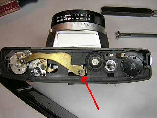
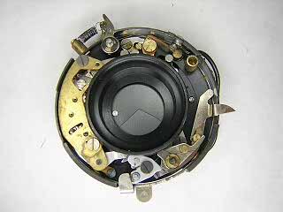
The interesting thing about this camera from the viewpoint of us tinkerers is the
way the shutter works. Overall, you have a standard mirror box mechanism and
a mostly standard leaf shutter. The unique part of the shutter is a special
drive ring located underneath the speed setting cam. This ring surrounds the outside
of the shutter base and drives the different parts of the mechanism. Unfortunately,
I don't have a a picture of this ring. One reason is that the ring sits on the
shutter base under spring tension and will not stay put unless you hold it down while
setting the speed cam back on. I needed a third hand to be able to take a picture!
As you disassemble the shutter, look closely when you remove the speed cam and you will
see this magic ring. There is a tab on the ring that pushes against a stud on the
blade operating ring. When at its resting position, this tab forces the blades open.
The hook attached to the main spring cam has a special cut-away that allows the blades
to be pushed open while the shutter is uncocked. On the outside of the control ring
there are several studs. One stud pushes against a spring operated lever to force the
ring back into position at the end of the cycle. Another stud pushes on the shutter
release. In addition, there is a brass lever attached to the ring that holds
back the diaphragm until the just before the shutter fires. This allows full
aperture focusing and metering.
Study this ring closely to understand how the shutter is controled.
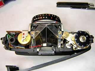
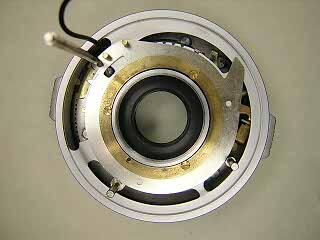
The auto-exposure system is a fairly typical needle capture system. The meter
unit is rotated by a gear driven screw. This adjusts the exposure for different
shutter speed and film speed settings. Re-adjusting the meter position turned into
quite an adventure. So, be sure and carefully measure the initial position of the
screw that pushes the meter back and forth before disassembly. I forgot to do this
and had to reset the meter position by trial and error.
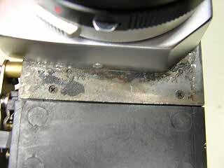
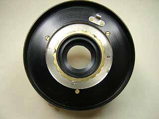
This camera came to me with an inoperable shutter and an stuck focus ring.
Fortunately, the shutter simply needed cleaning to remove the grease
on the shutter blades.
However, because of the way the shutter works, you can't do a simple cleaning of the
blades if they become sticky. The blades are pulled back out of the way
and thus the speed setting cam and control ring have to be removed in order
to get the blades to close. You can't just remove these parts
because the gear that drives the meter position prevents them from being
lifted off. The only way to get the gear out is to remove the mirror cage
and then remove the worm screw on the other end of the gear shaft. So, it's
an almost complete disassembly just to clean the shutter on this camera.
As always when working on a plastic body camera, be careful about overtightening
screws. It is easy to strip out the plastic thread in the screw holes of the body.
|