A simple four-speed shutter used on the Argus A series of cameras.
If you are going to completely disassemble the shutter, remove the shutter from the camera first. These first
images show the shutter located on the camera. For simple cleaning, you can just remove the faceplate, speed cam,
and top cover to access the clockworks.
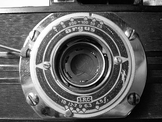 |
Unscrew the front and rear lens cells. Remove the two screws in the faceplate and lift the faceplate off.
|
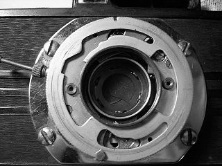 |
Lift off the speed setting cam. Note how the speed setting pins fit into the slots in the cam.
|
 |
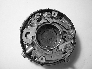
Remove the two screws in the cover and lift the cover off.
With the cover off you can reach all the parts for cleaning except the shutter blades and diaphragm.
|
 |
Remove the spring on the retard sector gear then remove the two screws in the retard cover and lift the cover off.
|
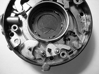 |
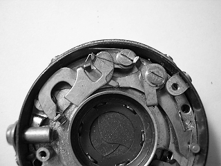
Lift out the sector gear, pallet and star wheel.
|
 |
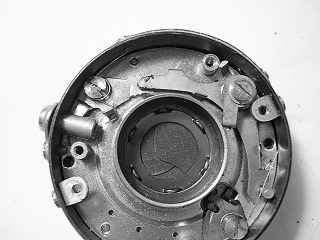
Remove the spring on the T/B lever assembly then remove the screw and lift the T/B lever off.
|
 |
Remove the screw on the outside shutter base that holds the cable release socket then slide
the cable release socket out. Unhook the trigger spring then remove the screw in the trigger and
the trigger lever.
The shutter shown here has a screw-in plunger to operate the shutter. Normally, you see a lever
on the trigger that extends out of the shutter base.
|
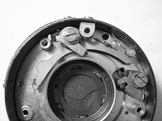 |
Unhook the mainspring from the main activating arm and the high-speed tensioning lever. Note: some versions
of this shutter lack the high-speed tensioning lever. Remove the screw and lift out the levers and spring.
Take careful note of the shim washers. They may be different in opening size and need to be replaced in the
same order they were removed.
Unhook the spring on the blade operating lever and remove the screw, lever and spring.
|
 |
Remove the two cover mounting brackets by removing the screws in the side of the shutter base.
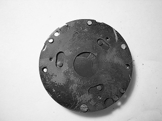
Remove the two screws in the inner base and lift the base out. It may be necessary to tilt the base
slightly to clear the screws for the aperture indicator.
|
 |
Turn the inner base over and remove the two screws in the blade cover plate. Lift off the cover.
|
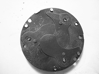 |
Lift out the three shutter blades. These are made of hard rubber and must be handled
carefully. To clean them, wipe the blades with a paper towel.
|
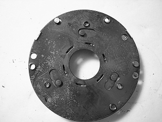 |
Lift the inner cover off. This cover is made so that it acts as a spacer to allow the blades to move freely.
Note which side goes towards the shutter base.
|
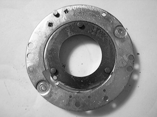 |
The blade activating ring lifts out.
|
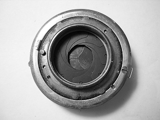 |
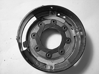
The aperture setting ring is removed from the back by removing one screw and lifting the ring out.
A slot in the ring mates with a tab on the diaphragm assembly and the ring may need to be tilted
during removal and installation.
|
 |
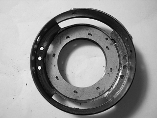
The diaphragm is held in place by two brackets. Remove the screws and lift the brackets out. Lift
out the diaphragm assembly. Note that the diaphragm may not open to its maximum size. On reassembly,
match the diaphragm opening to the lens opening in the inner shutter base and attach the operating
ring for the maximum aperture position (f/4.5 on this camera).
|
 |
The diaphragm base lifts out. Note the position of the pin that faces to the back of the shutter. If this
is not installed in the correct hole, the diaphragm opening will not match the aperture scale.
|
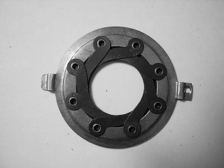 |
The diaphragm is a complete assembly that cannot be disassembled further. The blades are not made of metal and must be treated carefully. Wipe them off with a paper towel if they need cleaning.
|
Clean all parts with solvent before reassembly. Clean the bearings for the escapement gears by inserting a toothpick dampened with solvent. It may
be necessary to lightly oil the gear bearings.
Lubricate the speed setting cam plate where it rubs against the case and faceplate.
Lubricate the aperture setting ring where it rubs against the case.


