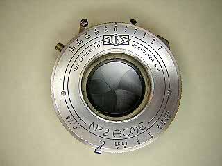
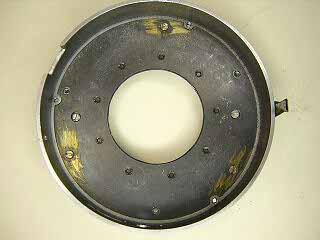
The Ilex Acme No. 2 shutter is an American manufactured shutter used on view and press cameras.
There are shutters with and without flash synchronization. The shutter shown here is
the non-synchronized version. One of the repair manuals I have shows a version
of this shutter with a double retard mechanism that allows for a wider range of speeds.
These are well built and reliable shutters that are still very usable today
and worth doing a complete cleaning on them. When I got this shutter it would
barely run at all. After a cleaning it runs dead-on at one second setting.
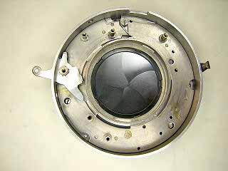
All the mechanism except for the aperture setting ring comes out from the front,
Thus, you may be able to do some work on the shutter without removing it from the camera or lens board.
 |
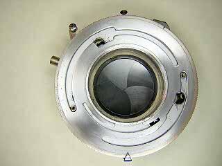
Unscrew and remove the front and rear lenses. Remove the two screws in the faceplate
and remove the faceplate.
|
 |
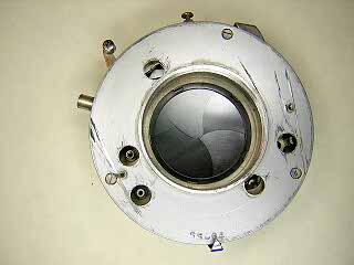
Take off the speed setting cam plate. This picture shows the speed cam at the setting for T.
|
 |
Remove the three screws in the shutter cover and remove the cover. The cover
may be tight and you will need to pry it gently to get it off.
|
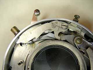 |
Disengage but don't remove the spring on the T/B levers. Remove the screw
and then lift the levers off.
|
 |
Underneath the T/B levers is the press-focus catch and the release latch.
Unhook the spring on the press-focus catch and remove the catch.
Unhook the spring on the trigger and remove the screw, washer and spring
from the trigger. The washer on this camera has a counter-sunk side for
the screw. Remember to put the counter-sunk side up when reinstalling the washer .
|
 |
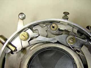
Remove the screw, lever and washer that sits over the escapement. This lever
pushes the pallet back during cocking so that the escapement can run
into place without having to run against the pallet.
|
 |
Note the way the cocking lever sits against the pinion and the position
of the hook lever that drives the blades. On reassembly you have to position this
pinion so that the hook for the blade operating ring is in this same position.
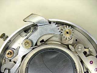
Remove the screw and washer on the cocking arm, unhook the main spring
and lift the spring and arm off. There should be some washers on the post
underneath the cocking arm. Remove these as well. Remember to hold a finger
over the mainspring while unhooking the spring. This is a powerful spring
and can fly off as you release the tension.
With the cocking arm out of the way, you can remove the release latch.
|
 |
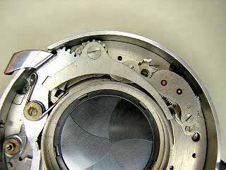
The escapement retard is held to the shutter with two screws at the
base of the escapement assembly. One of the screws is only visible
when the speed selector pin is in the position shown in this picture.
Remove the two screws in the base and lift the escapement assembly out.
Don't remove the screws in the top cover of the assembly
When reinstalling the retard assembly you have to hold the
speed selector pin up so that the hole for the top screw is visible.
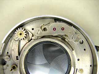
Remove the pinion and hook part. There is a spring that sits against
a stud on the underside of the hook that needs to be pulled back.
Remove the lever and washer underneath the pinion.
|
 |
Remove the knob on the trigger by unscrewing from underneath. Remove the
cable release tube by removing the two screws on the outside of the case.
There is a small pin inside the tube that will fall out. The press-focus
button can be unscrewed as well, but it is not necessary. I took it off
to clean it.
The shutter base is held by three screws. One of the screws is under
the trigger. Swing the trigger down to access the screw. The screw at the
top holds two springs. The spring on the bottom is the blade closing spring
and sits in a notch on the blade operating lever stud.
With the three screws out, lift up on the right side of the shutter base
and tilt the base slightly. You have to slide the base sideways so that
the trigger comes out through the slot in the side of the case.
|
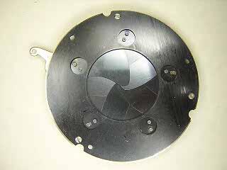 |
To remove the blades for cleaning or replacement, turn the base over
and remove the three screws. Carefully lift the cover plate off. There
are three spacers and washers underneath this plate (see next picture)
that can fall off when you lift the cover plate.
|
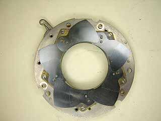 |
Each shutter blade has a reinforcing spacer on it. The rearmost blade (on top
looking from the rear) has the spacer underneath the blade. This blade goes on last.
The blades are installed moving in a counter-clockwise direction.
Look closely and you can see the spacers and washers. Note that one of the washers
is cut so that it does not interfere with a screw hole.
|
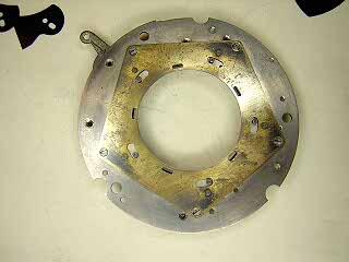 |
Remove the five screws in the brass plate and lift the plate off.
On this shutter, someone had already made a scratch mark to
indicate the orientation of the plate. I don't know if it's important
to get the plate back exactly where it was, but I put it back like it
was. You should probably do the same.
With the brass plate off you can lift the blade operating ring out.
|
 |
Move the aperture setting ring to the maximum aperture position and
you can then remove the two screws that hold the ring in place.
There are two spacers that come off with the ring.
To remove the diaphragm, remove the three screws in the cover and lift
the cover off. The diaphragm blades are permanently attached to the cover.
|