Beauty Canter
|
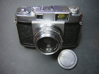
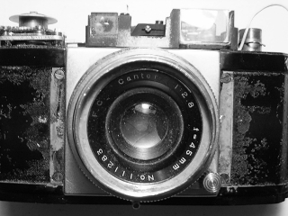
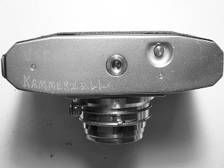
A fixed lens, leaf shutter rangefinder made by Taiyo-do Koki in the late 1950s. One interesting feature of this camera is the tinted viewfinder lens. Normally on cameras of this type, the beamsplitter is tinted to provide contrast with the reflected image. On this camera, there is a tinted lens in the viewfinder optics. The beamsplitter has only a small reflective spot in the middle. In addition, the Canter has an Albada finder. This particular camera had a pretty rough life. When I got it, the camera was very dirty and the front lens had cleaning scratches on it. It had impact damage resulting in a badly dented filter ring and a cracked top cover. The impact also dislodged the rangefinder mirror. The mirror subsequently got crushed and tiny peices of mirror were scattered inside the camera. Many pieces of glass had lodged in the helicoid grease and thus jammed the focus. Pieces of glass were also in the winding mechanism. In additiion, the shutter was dirty and running slow. As a result, I had to completely disassemble the camera, clean out the broken glass and dirt, then lubricate and adjust everything. I straightened the filter ring with a lens vice tool. Finally, I cut a new mirror for the rangefinder. Although the camera is certainly no "beauty" it looks like it works pretty well now. |
|
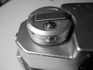 |
Open the back and hold the rewind fork while unscrewing the wind knob. There is a washer and bushing under the rewind knob. The large screw on the side of the rewind knob holds a spring for the button on top of the knob. This button has to be pulled aside to get the rewind crank to pop up. The small screw holds the crank and spring. These two screws can remain in place unless you need to disassemble the crank for repair. |
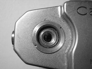 |
Unscrew slotted retaining nut underneath the rewind knob. |
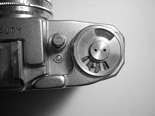 |
Remove the pin face screw in the winder and then lift off the film reminder cover, the film reminder dial and the wind lever. |
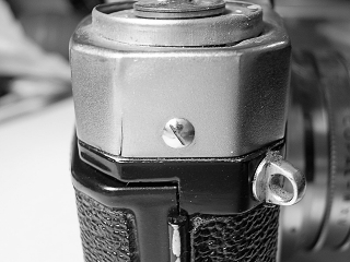 |
Remove the screw in the right side of the top cover. (Note the crack in the top cover!) Slowly lift up the top cover. The shutter release button falls out. The flash connector wire is attached to the top cover. Unsolder or clip this wire. Turn the top cover over and note the spring that provides tension to the shutter cocked indicator. This spring was tight around the tube it sits on, but you may want to remove it to prevent it getting lost during cleaning. |
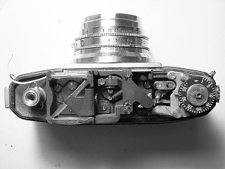 |
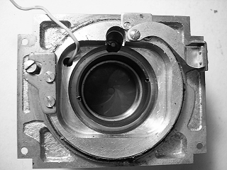
With the top cover off, you can access the rangefinder mirrors and lenses for cleaning. The rangefinder is held with two screws, one at each end towards the front of the rangefinder. Rangefinder adjustments are shown in detail at the bottom of this page. |
 |
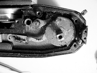
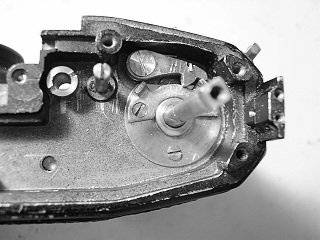
In between the rangefinder and film counter are shutter release and shutter wound indicator. These pieces are loose and should be removed before further diassembly. Normally its not necessary to remove the film counter. I had to remove it to clean out the glass fragments and dirt. Remove the two screws holding the stop (on the right edge of the camera) and remove the stop. Remove the screws holding the assembly and lift the film counter off. Carefully note the positions of the springs before removing the film counter. In this picture you can see where the rangefinder mirror is missing |
 |
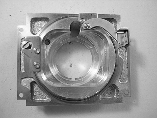
Pull off the leatherette from the front and remove the four screws around the front. These screws were stuck from glue on this camera. I had to add lacquer thinner around the heads of the screws to get them out. The shutter and focus assembly will lift off. The flash wire has to be pulled through the slot under the rangefinder. It is easier if you remove the rangefinder first. Behind the front panel is the winder pinion. This pinion has a spring in the tube that should be removed so that it doesn't get lost. |
 |
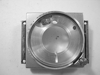
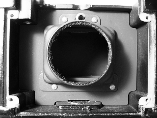
To remove the shutter, turn the front panel over and unscrew the retaining ring. Lift the shutter off, pulling the flash wire through. In this picture the rear lens has been removed. This isn't necessary, but it helps to prevent accidently scratching the lens if the spanner wrench slips while removing the retaining ring. To remove the front lens, unscrew the filter ring then unscrew the lens. Cleaning the Copal MXV is covered on another page. |
 |
In order to disassemble the helicoid, remove the screw in the shutter release lever and lift the lever off then remove the rangefinder follower plate and the helicoid guide plate. The guide post can stay attached. |
 |
From the front, unscrew the inner helicoid barrel, noting the position where the pieces separate. It isn't necessary to remove the shutter release part from the helicoid, but you may want to remove it for cleaning. The DOF scale is held to the inner helicoid with three setscrews. Other than for replacement, it isn't necessary to remove the DOF scale. (On this camera, I couldn't get the DOF scale off even with the screws removed.) Remove the two screws in the focusing knob and lift the knob out. Unscrew the outer helicoid barrel from the mounting plate counting the number of turns. It isn't necessary to remove the focus scale. To remove it for cleaning, back out the setscrews and lift the ring off. |
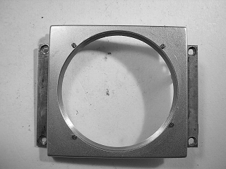 |
Remove the four screws in the decorative panel and lift the panel off. The two screws on the bottom serve as stops for the focus ring. |
 |
It is not necessary to remove the bottom cover in order to remove the shutter. If you need to get to the winder gears, remove the screws in the bottom cover and lift the cover off, The rewind release button falls out. |
 |
Remove the screws in the cover plate and remove the plate. Note the position of the spring on the rewind release catch. This catch has to sit against the rim of the rewind release button. During reassembly, pull the catch back and then set the button in place before putting the bottom cover back on. |
 |
Remove the spring on the rewind release catch, unscrew the retaining nut and lift the catch off. Remove the screw in the large cam and lift the cam off. |
 |
Unhook the spring on the pawl, remove the screw and lift off the pawl. Lift out the ratchet. |
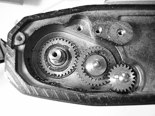 |
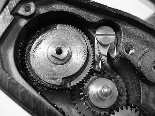
The bottom gear is attached to the takeup spool. I couldn't see how to remove it, so I cleaned it in place. (I think there is a snap ring around the takeup spool.) The idler gear and sprocket drive gear cannot be removed until the sprocket shaft is removed. (See next picture.) |
 |
In order to remove the film sprocket shaft, remove the four screws around the light shield in the front and lift off the light shield and cover underneath it. Turn the sprockets until the set screw is visible then remove the set screw. You can then pull the sprocket shaft out from the bottom. |
 |
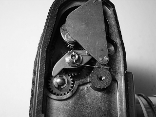
Remove the snap ring around the wind shaft and then lift off the cams underneath. These parts were very tight on this camera, but they do simply lift off. There is a spacer that is removed next. |
 |
Remove the screws in the cover over the winding rack, remove the cover and then the winder rack and lever.
Remove the winder cam from the winder shaft. |
 |
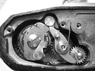
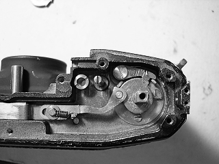
Remove the screw in the pawl and lift out the pawl and spring. Remove the screws in the bottom of the winder base and pull up the winder shaft and base. The wind shaft has a coiled spring around it with the end of the spring inserted into a slot in the base. When reassembling these parts, I found it was easiest to install the pawl first, then pull the pawl back while inserting the winder shaft and base. |
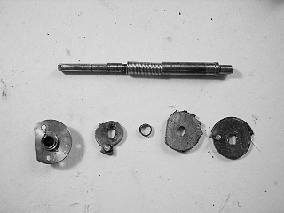 |
This picture shows the winder shaft with spring and the cams in the winder. |
Notes
|
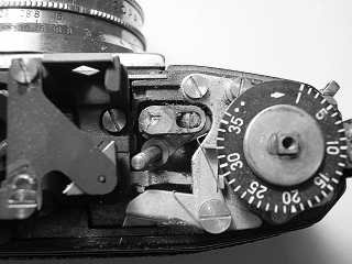
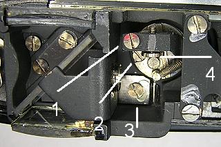
Rangefinder adjustment is made with the screws in the center of the rangefinder. Loosen the screw in the clamp (1) and then turn the adjustment knob (4) until the horizontal alignment is correct. The screw in the cam follower (2) adjusts the rate of change and can probably be left alone. Vertical alignment is made by turning the screw that raises and lowers the beamsplitter and internal lens (3). |
To adjust the focus, set the lens for proper focus at infinity, then back out the set screws in the focus scale and move the scale to the infinity position. Re-tighten the screws.
Reassembly of the top cover is easier if you wind the camera first. This causes the cocked indicator to pop up and it will then stay in position. Insert the shutter release button into the cover and hold it in place while lowering the cover down. Make sure the cocked indicator goes into the hole in the cover as you lower the cover.